


SPI9000 Inverter Unit FI9 – FI14 User Manual
2-4 For more information visit: www.EatonElectrical.com MN04004002E
September 2006
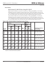
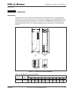
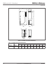
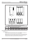
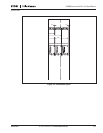
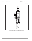
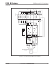
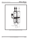
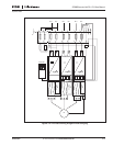
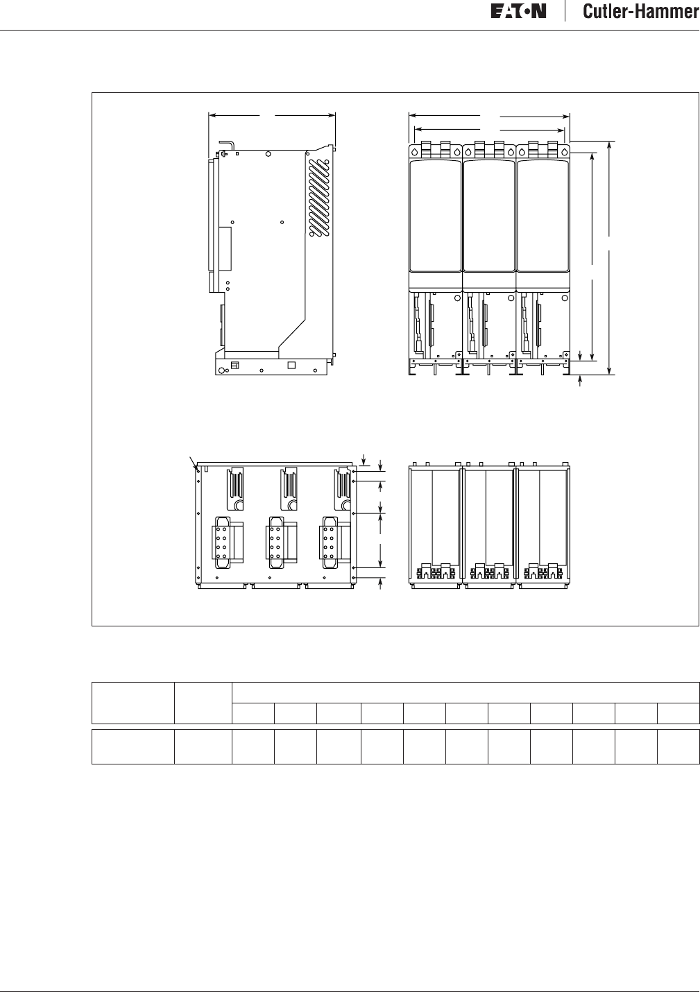
Figure 2-4: SPI9000 FI13 Inverter Dimensions (FI14 Is a Double FI13)
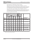
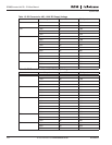
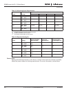
Table 2-4: SPI9000 FI13 Inverter Dimensions (FI14 Is a Double FI13)
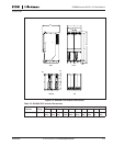
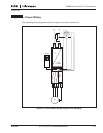
Fan Cooling
Frames FI9 to FI14
Enough free space must be left around the inverter to ensure sufficient air circulation and
cooling. You will find the required dimensions for free space Table 2-5.
If several units are mounted on top of each other, the required free space equals 2 * C (see
Figure 2-5). Moreover, the outlet air used for cooling by the lower unit must be directed away
from the air intake of the upper unit. When planning the cooling for the space, take into
consideration that the inverter’s heat loss is 2.5% of the nominal capacity.
Inverters Voltage
Approximate Dimensions in Inches (mm)
W1 W2 H1 H2 H3 D1 D2 D3 D4 D5 Dia.
SPI820 – H10 480V 27.9
(708)
26.7
(677)
41.5
(1055)
37.4
(950)
2.46
(62.5)
22.3
(566)
1.1
(27)
1.6
(40)
9.6
(245)
5.9
(150)
.37
(9.5)
H2
H3
FrontSide
Dia.
D5
D4
D3
D3
D2
TopBottom
H1
W2
W1
D1