


SPI9000 Inverter Unit FI9 – FI14 User Manual
2-6 For more information visit: www.EatonElectrical.com MN04004002E
September 2006
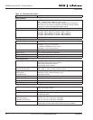
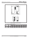
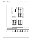
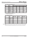
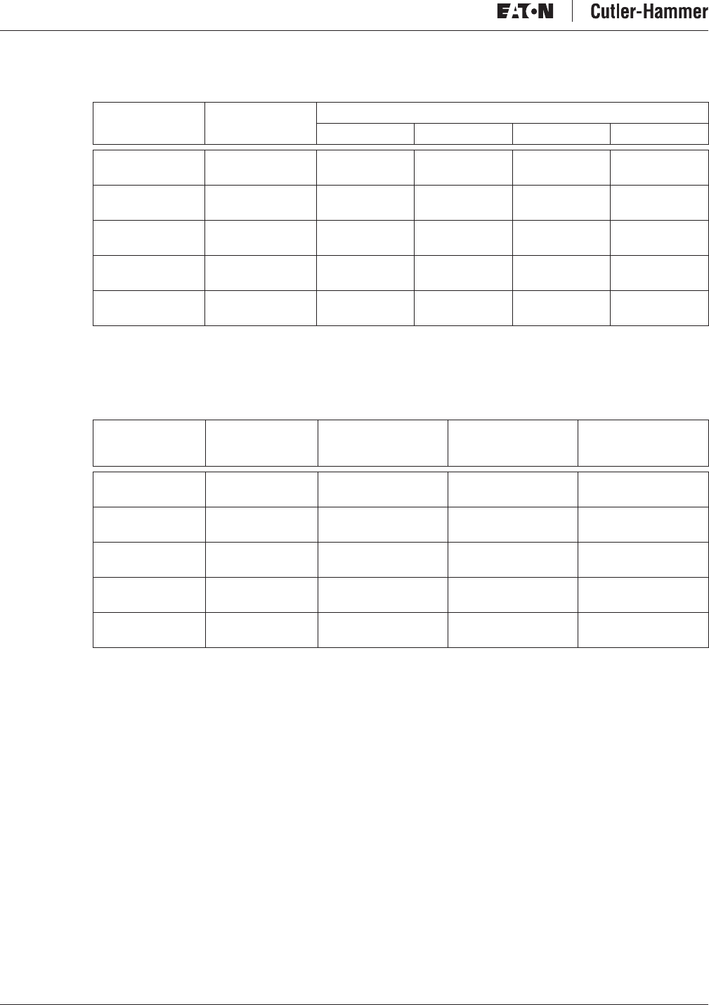
Table 2-5: Mounting Space Requirements
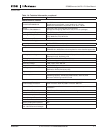
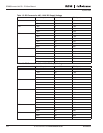
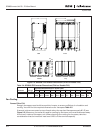
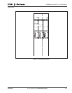
Table 2-6: Required Cooling Air
Power Losses
Raising the switching frequency of the drive, to reduce motor noise for example, inevitably
affects the power losses and cooling requirements. For more information, contact Eaton.
Frame Voltage
Approximate Dimensions in Inches (mm)
ABB
2
C
FI9 380 – 500V
525 – 690V
7.9 (200) .79 (20) 3.9 (100)
FI10 380 – 500V
525 – 690V
7.9 (200) .79 (20) 3.9 (100)
FI12 380 – 500V
525 – 690V
7.9 (200) .79 (20) 0 3.9 (100)
FI13 380 – 500V
525 – 690V
7.9 (200) .79 (20) 0 3.9 (100)
FI14 380 – 500V
525 – 690V
7.9 (200) .79 (20) 0 3.9 (100)
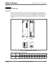
A = free space above the inverter
B = distance between inverter and cabinet wall
B
2
= distance between two inverters
C = free space underneath of the inverter
Frame Voltage
Greatest Possible
Heat Loss (kW)
Cooling Air
Required (cfm)
Minimum Air
Exhausting Hole
on Switchgear (in
2
)
FI9 380 – 500V
525 – 690V
4.8
4.6
677 77.5
FI10 380 – 500V
525 – 690V
8.3
9.1
824 93
FI12 380 – 500V
525 – 690V
16.5
18.0
1648 186
FI13 380 – 500V
525 – 690V
23.0
26.0
2472 279
FI14 380 – 500V
525 – 690V
46.0
52.0
2 x 2472 2 x 279