


SPI9000 Inverter Unit FI9 – FI14 User Manual
MN04004002E
For more information visit: www.EatonElectrical.com 5-1
September 2006
Chapter 5 — Menu Information
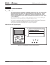
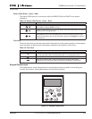
Keypad Operation
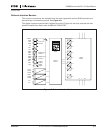
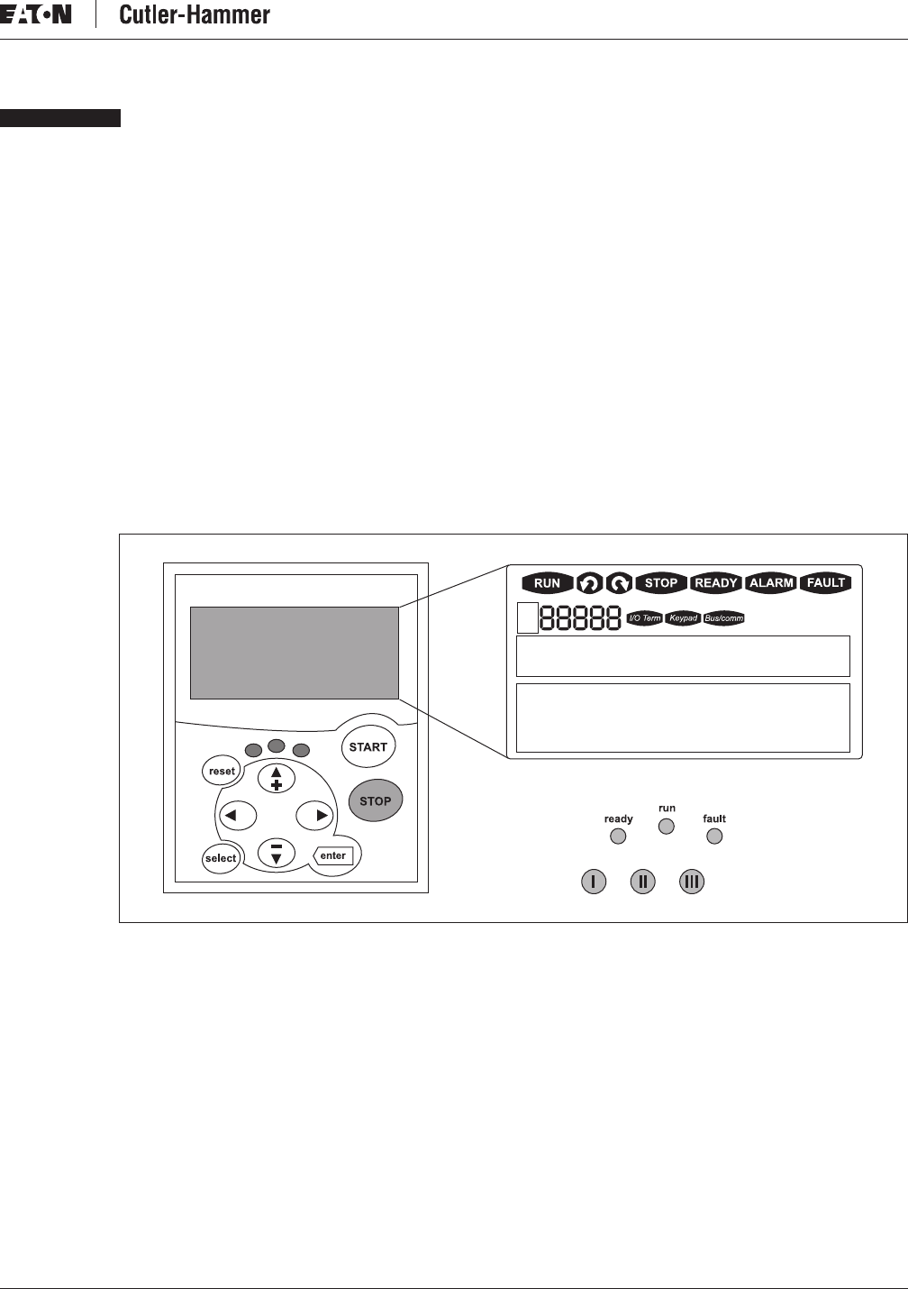
The control keypad is the link between the SPI9000 inverter and the user. The control keypad
features an alphanumeric display with seven indicators for the Run status (RUN, counter-
clockwise, clockwise, READY, STOP, ALARM, FAULT) and three indicators for the control
place (I/O term/Keypad/BusComm). There are also three Status Indicator LEDs (green – green
– red), see Page 5-3.
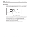
The control information, i.e. the menu number, description of the menu or the displayed
value and the numeric information are presented on three text lines.
The inverter is operable through the nine pushbuttons of the control keypad. Furthermore,
the buttons can be used in setting parameters and monitoring values.
The keypad is detachable and isolated from the input line potential.
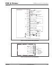
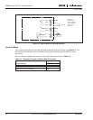
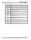
Indicators on the Keypad Display
Figure 5-1: Control Keypad and Drive Status Indications