


SPI9000 Inverter Unit FI9 – FI14 User Manual
5-2 For more information visit: www.EatonElectrical.com MN04004002E
September 2006
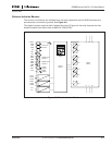
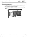
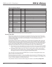
Drive Status Indicators
The drive status symbols tell the user the status of the motor and the inverter. In addition,
they tell about possible irregularities detected by the motor control software in motor or
inverter functions.
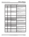
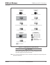
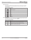
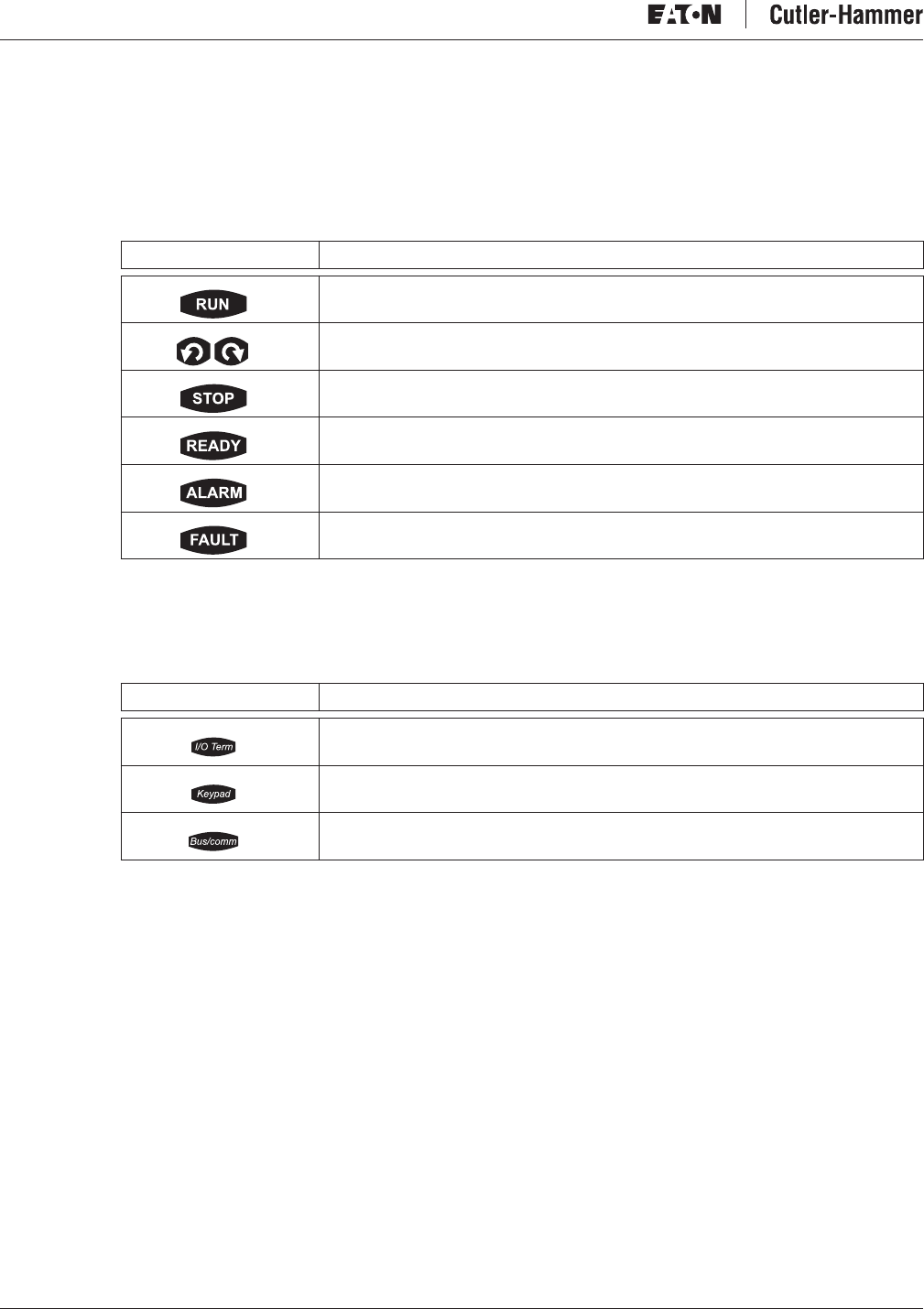
Table 5-1: Drive Status Indicators
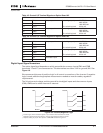
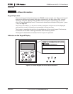
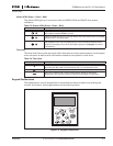
Control Place Indicators
The symbols I/O Term, Keypad and Bus/Comm (see Table 5-2) indicate the choice of control
place made in the Keypad control menu (M3) (see Page 5-9).
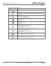
Table 5-2: Control Place Indicators
Indicator Description
Motor is running. Blinks when the stop command is given, but the frequency
is still ramping down.
Indicates the direction of motor rotation.
Indicates that the drive is not running.
Lights up when AC power is on. In case of a trip, the symbol will not light up.
Indicates that the drive is running outside a certain limit and a warning is
given.
Indicates that unsafe operating conditions are encountered and the drive was
stopped.
Indicator Description
I/O terminals are selected as the control place, i.e., START/STOP commands
or reference values, etc. are given through the I/O terminals.
Control keypad is selected as the control place, i.e., the motor can be started
or stopped or its reference values, etc. altered from the keypad.
The inverter is controlled through a fieldbus.