


SPI9000 Inverter Unit FI9 – FI14 User Manual
MN04004002E
For more information visit: www.EatonElectrical.com 2-1
September 2006
Chapter 2 — Mounting
Dimensions
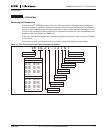
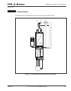
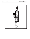
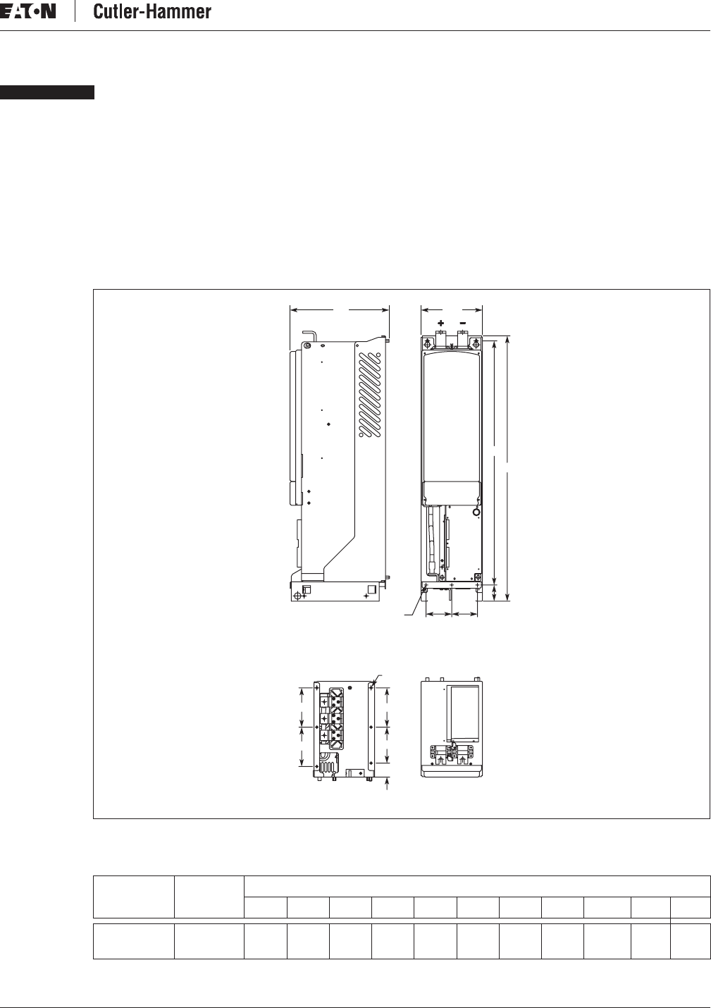
The inverter can be mounted in a vertical position on the back plane of a cubicle. Enough
space must be reserved around the inverter to ensure sufficient cooling, see Figure 2-5. You
must follow the minimum dimensions for installation, see Tables 2-5 and 2-6. Also make sure
that the mounting plane is relatively even. The inverter is fixed with four screws (or bolts,
depending on the unit size). The following pages show the dimensions for the IP00 power
module.
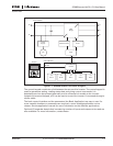
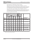
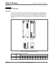
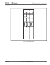
Figure 2-1: SPI9000 FI9 Inverter Dimensions
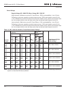
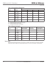
Table 2-1: SPI9000 FI9 Inverter Dimensions
Inverters Voltage
Approximate Dimensions in Inches (mm)
W1 W2 H1 H2 H3 D1 D2 D3 D4 Dia. 1 Dia. 2
SPI100 – 170 480V/575V 9.41
(239)
3.94
(100)
40.63
(1032)
37.40
(950)
2.46
(62.5)
15.20
(386)
2.12
(53.9)
5.51
(140)
6.03
(153.1)
.18
(4.6)
.37
(9.5)
W2 W2
H1
Dia. 1
H3
H2
D3 D3
Dia. 2
D4
D3
D2
FrontSide
TopBottom
W1D1