


SPI9000 Inverter Unit FI9 – FI14 User Manual
4-4 For more information visit: www.EatonElectrical.com MN04004002E
September 2006
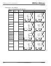
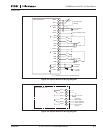
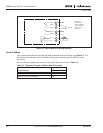
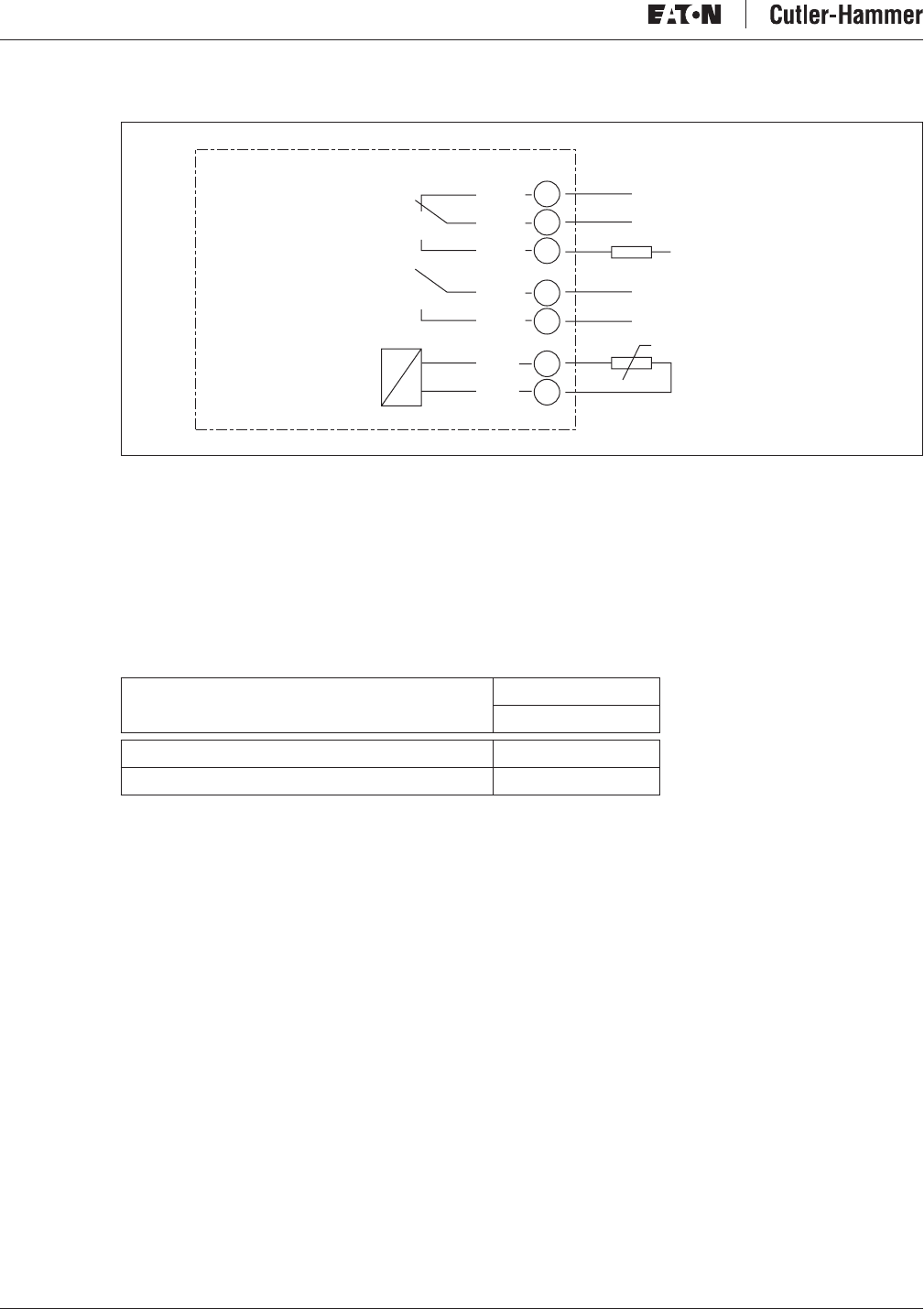
Figure 4-7: Option Board A3 Wiring Diagram
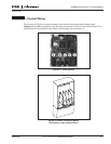
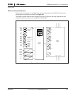
Control Cables
The control cables shall be at least 20 AWG screened multicore cables, see Table 4-1. The
maximum terminal wire size is 14 AWG for the relay terminals and 16 AWG for other
terminals.
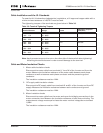
You can find the tightening torques of the option board terminals in Table 4-1.
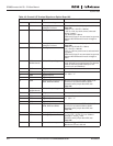
Table 4-1: Tightening Torques of Option Board Terminals
26
25
23
22
21
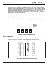
RO1/1
RO1/2
RO1/3
RO2/1
RO2/2
R
L
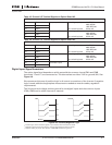
Switching:
<8A / 24V DC
<2kVA / 250V AC
<0.4A / 125V DC
Continuously
<2 Arms
AC / DC
Basic Relay Board A3
29
28
TL1+
+t
TL1
–
Terminal Screw
Tightening Torque
lb-in.
Relay and thermistor terminals (screw M3) 4.5
Other terminals (screw M2.6) 1.8