


SPI9000 Inverter Unit FI9 – FI14 User Manual
MN04004002E
For more information visit: www.EatonElectrical.com 3-17
September 2006
Cable Installation and the UL Standards
To meet the UL (Underwriters Laboratories) regulations, a UL approved copper cable with a
minimum heat-resistance of +60/75°C must be used.
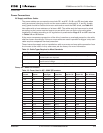
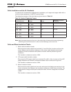
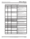
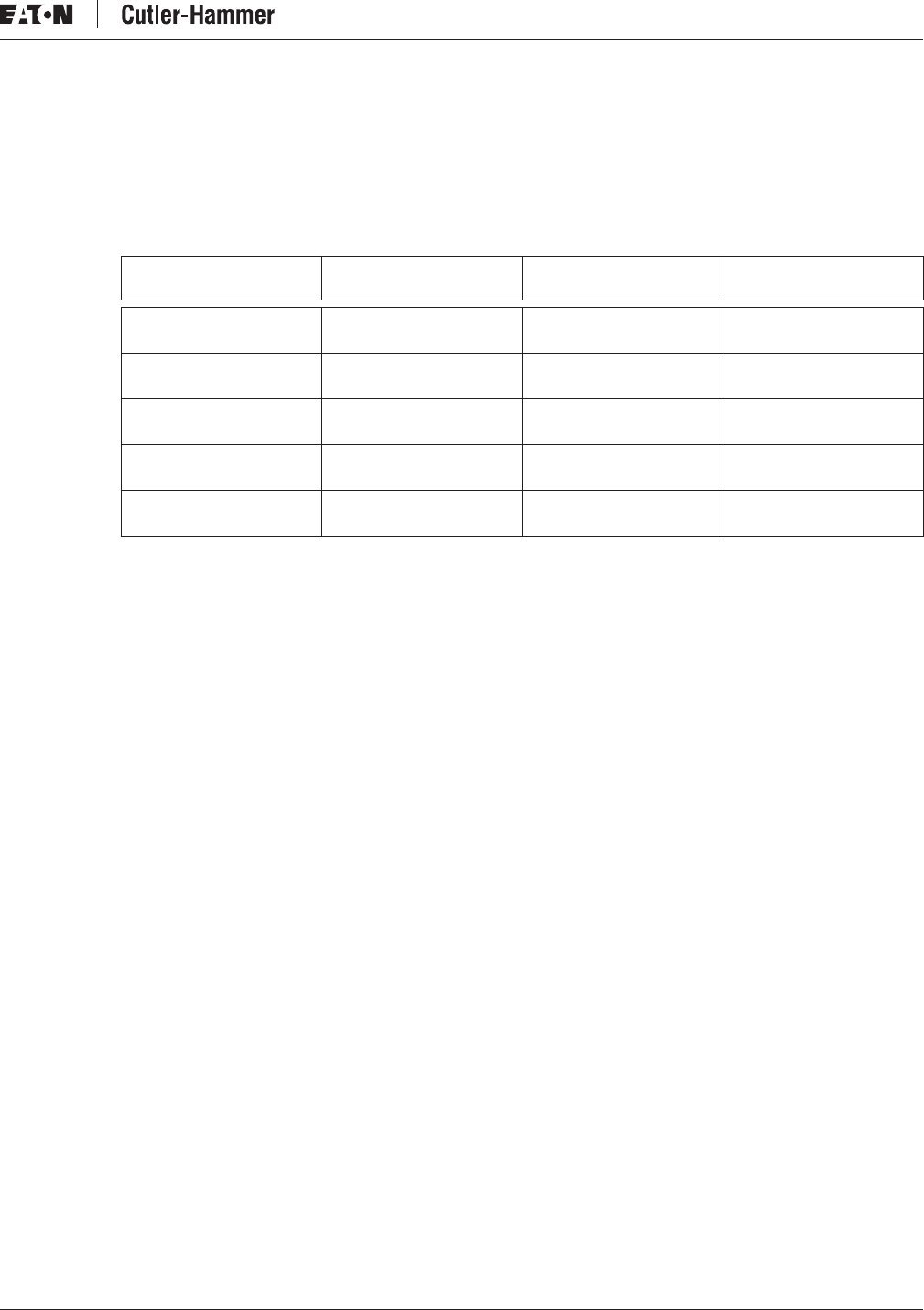
The tightening torques of the terminals are given below in Table 3-9.
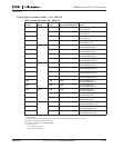
Table 3-9: Terminal Tightening Torques
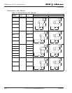
ᕃ
Tightening torque of terminal connection to the isolative base.
Note: Apply counter torque to the nut on the other side of the terminal when tightening/
loosening the terminal screw in order to avoid damage to the terminal.
Cable and Motor Insulation Checks
1. Motor cable insulation checks
Disconnect the motor cable from terminals U, V and W of the inverter and from the
motor. Measure the insulation resistance of the motor cable between each phase
conductor as well as between each phase conductor and the protective ground
conductor.
The insulation resistance must be >1MΩ.
2. DC supply cable insulation checks
Disconnect the DC supply cable from terminals B- and B+ of the inverter and from DC
supply. Measure the insulation resistance between each conductor and ground.
The insulation resistance must be >1MΩ.
3. Motor insulation checks
Disconnect the motor cable from the motor and open the bridging connections in the
motor connection box. Measure the insulation resistance of each motor winding. The
measurement voltage must equal at least the motor nominal voltage but not exceed
1,000V.
The insulation resistance must be >1MΩ.
Nominal Current Voltage Frame
Tightening Torque in
in-lb (Nm)
ᕃ
140 – 245
100 – 170
380 – 500V
525 – 690V
FI9 340 (40)
300 – 460
208 – 325
380 – 500V
525 – 690V
FI10 340 (40)
520 – 920
385 – 650
380 – 500V
525 – 690V
FI12 340 (40)
1030 – 1300
920 – 1030
380 – 500V
525 – 690V
FI13 340 (40)
1600 – 2300
1300 – 1900
380 – 500V
525 – 690V
FI14 340 (40)