


SPI9000 Inverter Unit FI9 – FI14 User Manual
4-6 For more information visit: www.EatonElectrical.com MN04004002E
September 2006
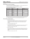
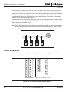
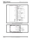
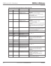
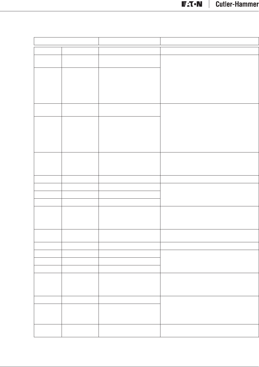
Table 4-2: Control I/O Terminal Signals on Option Board A9
Terminal Signal Technical Information
1 +10 Vref Reference voltage Maximum current 10 mA
2 AI1+ Analog input,
voltage or current
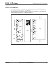
Selection V or mA with jumper block X1 (see
Page 4-8)
Default: 0 to +10V (Ri = 200 kΩ)
(-10V to +10V Joy-stick control, selected
with a jumper)
0 to 20 mA (Ri = 250 Ω)
Differential input if not connected to ground;
Allows ±20V differential mode voltage to
GND
3 GND/AI1– Analog input common
4 AI2+ Analog input,
voltage or current
Selection V or mA with jumper block X1 (see
Page 4-8):
Default: 0 to 20 mA (Ri = 250 Ω)
0 to +10V (Ri = 200 kΩ)
(10V to +10V Joy-stick control, selected with
a jumper)
Differential input if not connected to ground;
Allows ±20V differential mode voltage to
GND
5 GND/AI2– Analog input common
6 24 Vout
(bidirectional)
24V auxiliary voltage ±15%; maximum current 250 mA all boards
total; 150 mA from single board. Can also be
used as external power backup for the
control unit (and fieldbus).
7 GND I/O ground Ground for reference and controls
8 DIN1 Digital input 1 R
i
= min. 5kΩ
18 – 30V = “1”
9 DIN2 Digital input 2
10 DIN3 Digital input 3
11 CMA Digital input common A for
DIN1, DIN2 and DIN3.
Must be connected to GND or 24V of I/O
terminal or to external 24V or GND
Selection with jumper block X3 (see
Page 4-8)
12 24 Vout
(bidirectional)
24V auxiliary voltage Same as terminal #6
13 GND I/O ground Same as terminal #7
14 DIN4 Digital input 4 R
i
= min. 5kΩ
18 – 30V = “1”
15 DIN5 Digital input 5
16 DIN6 Digital input 6
17 CMB Digital input common B for
DIN4, DIN5 and DIN6
Must be connected to GND or 24V of I/O
terminal or to external 24V or GND
Selection with jumper block X3 (see
Page 4-8)
18 AO1+ Analog signal (+output) Output signal range:
Current 0(4) – 20 mA, R
L
max. 500Ω or
Voltage 0 – 10V, R
L
>1kΩ
Selection with jumper block X3 (see
Page 4-8)
19 AO1- Analog output common
20 DO1 Open collector output Maximum U
in
= 48V DC
Maximum current = 50 mA