SPI9000 Inverter Unit FI9 – FI14 User Manual
MN04004002E
For more information visit: www.EatonElectrical.com 5-11
September 2006
Keypad Direction
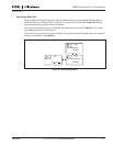
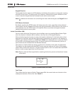
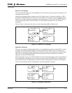
The keypad direction submenu (P3.3) displays and allows the operator to change the rotating
direction of the motor. This setting will not, however, influence the rotation direction of the
motor unless the keypad has been selected as the active control place.
Note: For additional information on controlling the motor with the keypad, see Pages 5-3 and
6-2.
STOP Button Activated
By default, pushing the STOP button will always stop the motor regardless of the selected
control place. You can disable this function by giving parameter 3.4 the value 0. If the value of
this parameter is 0, the STOP button will stop the motor only when the keypad has been
selected as the active control place.
Active Faults Menu (M4)
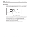
You can enter the Active Faults menu from the Main menu by pressing Menu Button Right
when the location indication M4 is visible on the first line of the keypad display.
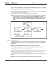
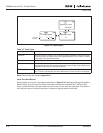
When a fault brings the inverter to a stop, the location indication F1, the fault code, a short
description of the fault, and the fault type symbol (see below) will appear on the display. In
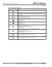
addition, the indication FAULT or ALARM (see Table 5-1) is displayed and, in case of a FAULT,
the red LED on the keypad starts to blink. If several faults occur simultaneously, the list of
active faults can be browsed with the Browser buttons.
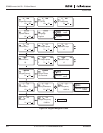
The memory of active faults can store a maximum of 10 faults in the order of appearance.
The display can be cleared with the RESET button and the read-out will return to the same
state it was in before the fault trip. The fault remains active until it is cleared with the RESET
button or with a reset signal from the I/O terminal.
Note: Remove external Start signal before resetting the fault to prevent unintentional restart
of the drive.
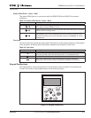
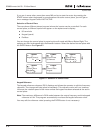
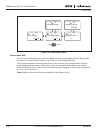
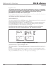
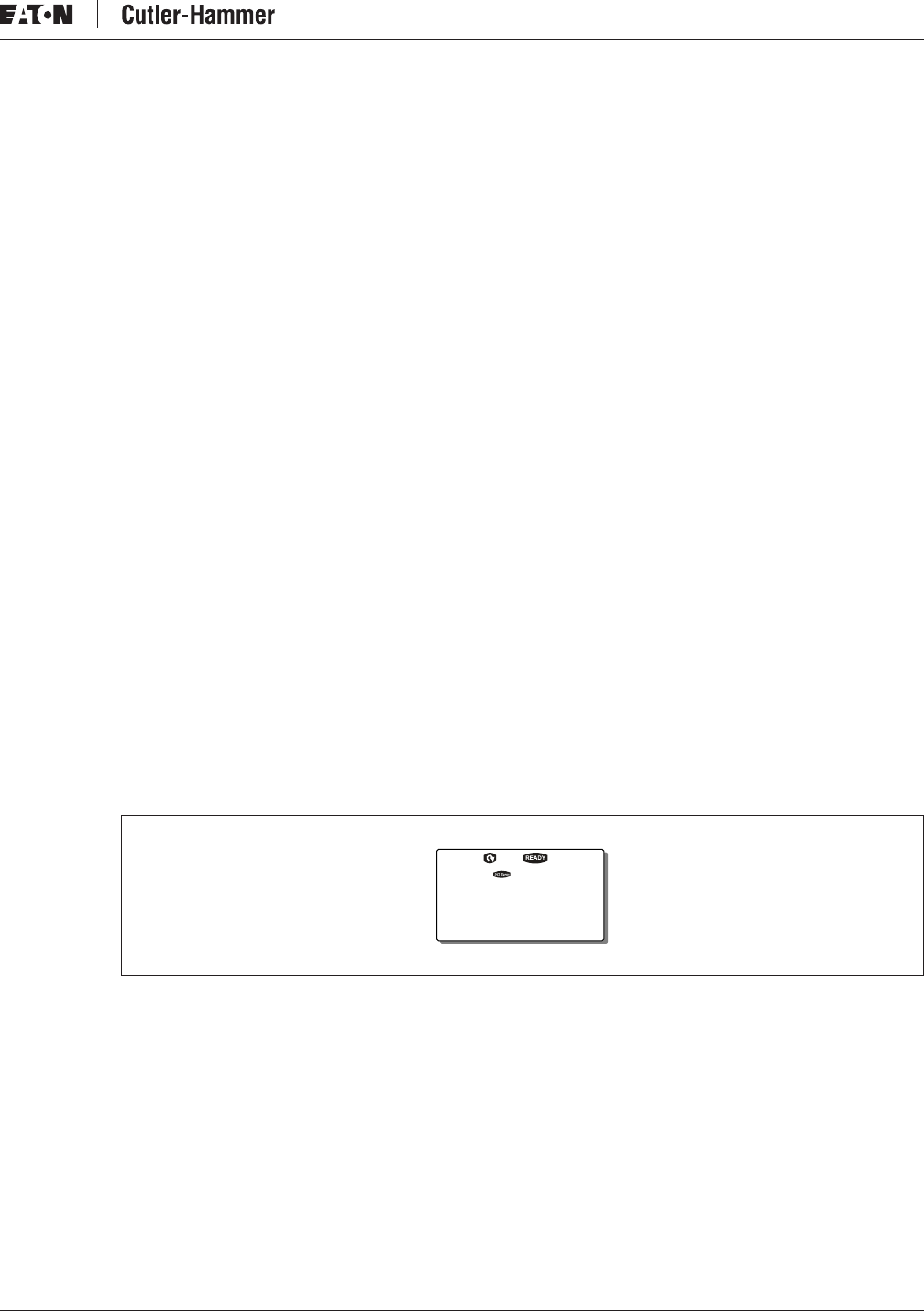
Figure 5-8: Normal State, No Faults
Fault Types
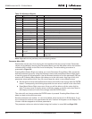
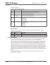
The inverter has four types of faults. These types differ from each other on the basis of the
subsequent behavior of the drive. See Table 5-7.
Active faults
MH
F0


