


SPI9000 Inverter Unit FI9 – FI14 User Manual
MN04004002E
For more information visit: www.EatonElectrical.com 5-13
September 2006
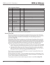
The data available are:
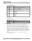
Table 5-8: Fault Time Recorded Data
ᕃ
Tells the user if the drive was at zero speed (< 0.01 Hz) when the fault occurred
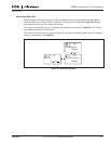
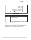
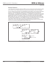
Real Time Record
If real time is set to run on the inverter, the data items T1 and T2 will appear as follows:
Table 5-9: Real Time Record
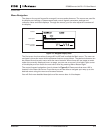
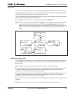
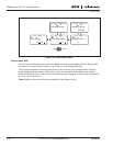
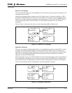
Fault History Menu (M5)
You can enter the Fault History menu from the Main menu by pressing Menu Button Right
when the location indication M5 is visible on the first line of the keypad display.
All faults are stored in the Fault History menu where you can browse them with the Browser
buttons. Additionally, the Fault Time Data Record pages (see Page 5-12) are accessible for
each fault. You can return to the previous menu any time by pressing Menu Button Left.
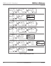
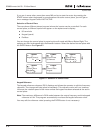
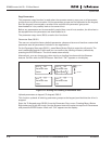
The memory of the inverter can store a maximum of 30 faults in order of appearance. The
number of faults currently in the fault history is shown on the value line of the main page
(H1➔H#). The order of the faults is indicated by the location indication in the upper left corner
of the display. The latest fault is indicated by F5.1, the one before that by F5.2 and so on. If
there are 30 uncleared faults in the memory, the next fault will erase the oldest fault from the
memory.
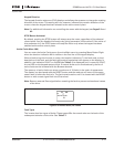
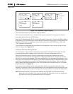
Pressing the ENTER button for about 2 to 3 seconds resets the whole fault history. The
symbol H# will change to 0.
Data Units Description
T.1 D Counted operation days (Fault 43: Additional code)
T.2 hh:mm:ss
(d)
Counted operation hours
(Fault 43: Counted operation days)
T.3 Hz
hh:mm:ss
Output frequency
(Fault 43: Counted operation hours)
T.4
T.5
T.6
T.7
T.8
A
V
%
%
V
Motor current
Motor voltage
Motor power
Motor torque
DC bus voltage
T.9
T.10
T.11
T.12
T.13
°C
—
—
—
—
Unit temperature
Run status
Direction
Warnings
Zero speed
ᕃ
Data Units Description
T.1 yyyy-mm-dd Counted operation days
T.2 hh:mm:SS,sss Counted operation hours