


SPI9000 Inverter Unit FI9 – FI14 User Manual
MN04004002E
For more information visit: www.EatonElectrical.com 4-7
September 2006
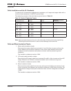
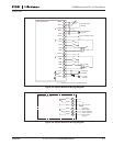
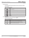
Table 4-3: Control I/O Terminal Signals on Option Board A2
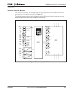
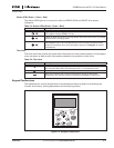
Table 4-4: Control I/O Terminal Signals on Option Board A3
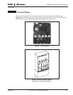
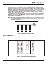
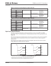
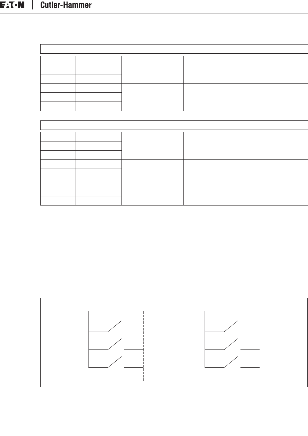
Digital Input Signal Inversions
The active signal level depends on which potential the common inputs CMA and CMB
(terminals 11 and 17) are connected to. The alternatives are either +24V or ground (0V). See
Figure 4-9.
We recommend the use of positive logic in all control connections of the inverter. If negative
logic is used, additional appropriate measures are needed to meet the safety regulation
requirements.
The 24 volt control voltage and the ground for the digital inputs and the common inputs
(CMA, CMB) can be either internal or external.
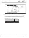
Figure 4-9: Positive/Negative Logic
ᕃ
Positive logic (+24V is the active signal) = Input is active when the switch is closed.
ᕄ
Negative logic (0V is the active signal) = Input is active when the switch is closed.
ᕅ
Requires setting of jumper X3 to position “CMA/CMB isolated from ground.”
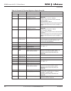
OPTA2
21 RO1/1 Relay output 1 Switching capacity 24V DC/8A
250V AC/8A
125V DC/0.4A
5V/10 mA
22 RO1/2
23 RO1/3 Min. switching load
24 RO2/1 Relay output 2 Switching capacity 24V DC/8A
250V AC/8A
125V DC/0.4A
5V/10 mA
25 RO2/2
26 RO2/3 Min. switching load
OPTA3
21 RO1/1 Relay output 1 Switching capacity 24V DC/8A
250V AC/8A
125V DC/0.4A
5V/10 mA
22 RO1/2
23 RO1/3 Min. switching load
24 RO2/1 Relay output 2 Switching capacity 24V DC/8A
250V AC/8A
125V DC/0.4A
5V/10 mA
25 RO2/2
26 RO2/3 Min. switching load
28 TI1+ Thermistor input
29 TI1-
DIN1
+
24V
DIN2
DIN3
CMA
Ground
DIN1
Ground
DIN2
DIN3
CMA
+
24V
ᕃ ᕄ
ᕅ