


SPI9000 Inverter Unit FI9 – FI14 User Manual
MN04004002E
For more information visit: www.EatonElectrical.com 4-9
September 2006
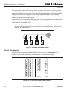
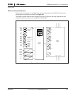
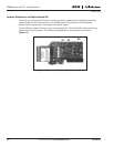
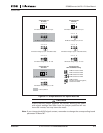
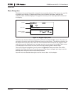
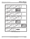
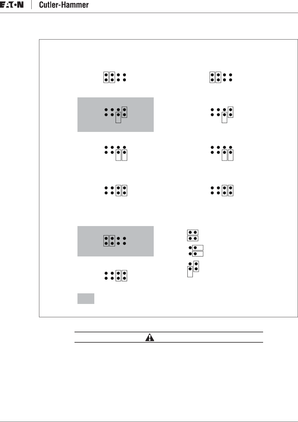
Figure 4-11: Jumper Selection for Option Board A9
CAUTION
Ensure that the jumper positions are correct. Running the motor
with signal settings that differ from the jumper positions will not
harm the inverter, but may harm the motor.
Note: If you change the AI/AO signal content, remember to change the corresponding board
parameter in Menu M7.
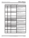
Jumper Block X1:
AI1 Mode
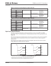
AI1 Mode: 0...20mA; Current Input
A B C D
A B C D
A B C D
AI1 Mode: Voltage Input; 0...10V
AI1 Mode: Voltage Input; 0...10V (Differential)
AI1 Mode: Voltage Input; -10...10V
A B C D
Jumper Block X6:
AO1 Mode
AI1 Mode: 0...20mA; Current Output
A B C D
A B C D
AO1 Mode: Voltage Output; 0...10V
= Factory Default
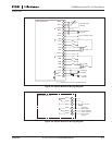
Jumper Block X2:
AI2 Mode
AI2 Mode: 0...20mA; Current Input
A B C D
A B C D
A B C D
AI2 Mode: Voltage Input; 0...10V
AI2 Mode: Voltage Input; 0...10V (Differential)
AI2 Mode: Voltage Input; -10...10V
CMB Connected to GND
A B C D
Jumper Block X3:
CMA and CMB Grounding
CMA Connected to GND
CMB Isolated from GND
CMA Isolated from GND
CMB and CMA
Internally Connected Together,
Isolated from GND