


SPI9000 Inverter Unit FI9 – FI14 User Manual
MN04004002E
For more information visit: www.EatonElectrical.com 3-15
September 2006
Installation Instructions
1. Before starting the installation, check that none of the components of the inverter are live.
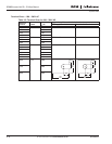
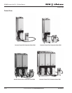
2. If the inverter is installed outside the cubicle, cabinet or device space, you need to install
a separate inverter cover in accordance with protection class IP21 requirements (see
Page 3-16. There is no need to install the inverter cover if the inverter is installed in a
cubicle, separate cabinet or device space.
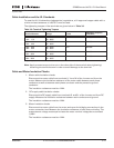
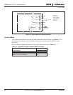
3. Place the motor cables sufficiently far from other cables:
– Avoid placing the motor cables in long parallel lines with other cables
– If the motor cables runs in parallel with other cables, note the minimum distances
between the motor cables and other cables given in Table 3-8.
– The given distances also apply between the motor cables and signal cables of other
systems.
– The maximum length of the motor cables is 984 feet (300m) (units with power
greater than 1.5 kW) and 328 feet (100m) (units with power from 0.75 to 1.5 kW).
– The motor cables should cross other cables at an angle of 90 degrees.
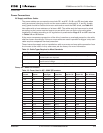
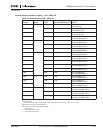
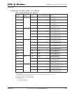
Table 3-8: Cable Distances
4. If cable insulation checks are needed, see Page 3-17.
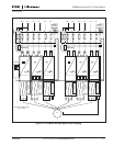
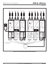
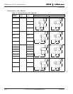
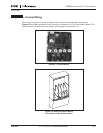
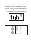
5. Connect the cables:
– Strip the motor and DC supply cables.
– Remove the screws of the cable protection plate. Do not open the cover of the power unit!
– Make holes into and pass the cables through the rubber grommets on the bottom of
the power unit. The rubber grommets are delivered in a separate bag.
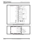
– Connect the DC supply, motor and control cables into their respective terminals.
– For information on the installation of greater units, please contact Eaton or your
local distributor.
– For Information on cable installation according to UL regulations, see Page 3-17.
– For information on cable installation according to EMC regulations, see Table 3-1.
– Make sure that the control cable wires do not come in contact with the electronic
components of the unit.
– If an external brake resistor (optional) is used, connect its cable to the appropriate
terminal.
– Check the connection of the ground cable to the motor and the inverter terminals
marked with .
– Connect the separate shield of the power cable to the ground terminals of the
inverter, motor and the supply center.
– Attach the cable protection plate with the screws.
– Ensure that the control cables or the cables of the unit are not trapped between the
frame and the protection plate.
Distance Between Cables in
Inches (m)
Shielded
Cable in Feet (m)
11.8 (.3)
39.4 (1.0)
≥ 193 (59)
≤ 656 (200)