


SPI9000 Inverter Unit FI9 – FI14 User Manual
MN04004002E
For more information visit: www.EatonElectrical.com 5-3
September 2006
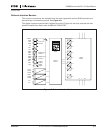
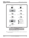
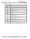
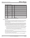
Status LEDs (Green – Green – Red)
The status LEDs light up in connection with the READY, RUN and FAULT drive status
indicators.
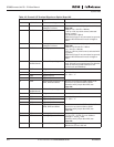
Table 5-3: Status LEDs (Green – Green – Red)
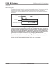
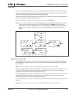
Text Lines
The three text lines provide the users with information on their present location in the keypad
menu structure as well as with information related to the operation of the drive.
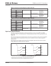
Table 5-4: Text Lines
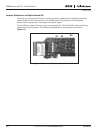
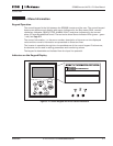
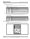
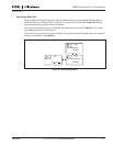
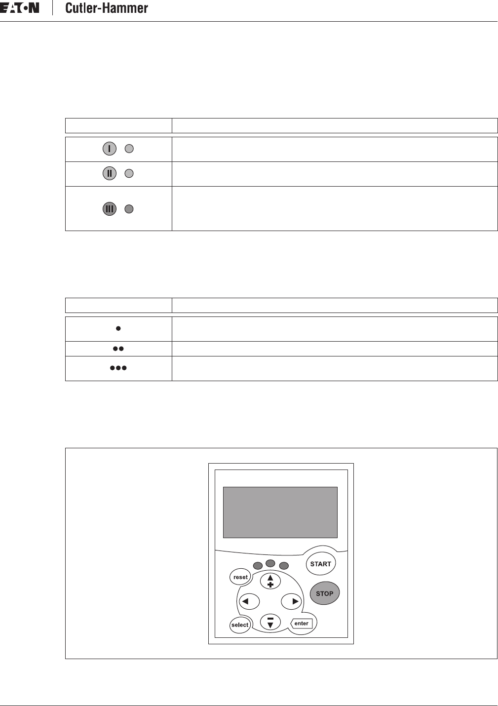
Keypad Pushbuttons
The alphanumeric control keypad has nine pushbuttons that are used for controlling the
inverter (and motor), setting parameters and monitoring values.
Figure 5-2: Keypad Pushbuttons
Indicator Description
Lights up when the AC power is connected to the drive. Simultaneously, the
drive status indicator READY is lit up.
Lights up when the drive is running. Blinks when the STOP button is pushed
and the drive is ramping down.
Lights up when unsafe operating conditions are encountered and the drive
was stopped (Fault Trip). Simultaneously, the drive status indicator FAULT
blinks on the display and a fault description appears (see Page 5-11, Active
Faults Menu).
Indicator Description
Location indicator: Displays the symbol and number of the menu, parameter,
etc. Example: M2 = Menu 2 (Parameters); P2.1.3 = Acceleration time.
Description line: Displays the description of the menu, value or fault.
Value line: Displays the numerical and textual values of references,
parameters, etc. and the number of submenus available in each menu.