


Appendix C
Cable Pinout
s
This append ix lists the cables and co n nector pinout assignments for the cables used
with the ERX-7xx models and ERX-14xx models. It contains the following sections:
SRP I/O Module on page 143
CT1andCE1I
/O Modules on page 146
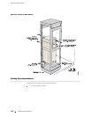
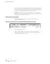
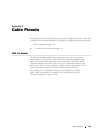
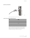
SRP I/O Module
The SRP I/O module provides two managem en t ports. You can connect a
console dir
ectly to the RS-232 serial port using a shielded straight-through
cable with a female DB-9 connector on one end and a male DB-25 with a
crossover adapter on the DB-25 end. This port is called the serial port, the
RS-232 por
t, o r the c on so le serial p o rt. Figure 52 shows the location of the
serial port and the sequence of the pins in the RS-232 connector.
The console port is considered a data term in a l equipment interface
(DTE). Direct connection to a terminal or PC (which also have DTE
interfac
es) requires a crossover cable.
SRP I/O Module 143