


ERX 8.0.x Hardware Guide
Installing Components for Line Module Redundancy
A spare lin e mod ul e provides redundancy for a group of identical line
modules for ER
X-7xx and ERX-14xx models only.
NOTE: The ERX-310 router does not support line module redundancy.
For line module
redundancy to operate, you must install:
The line module
s,includingthesparelinemodule
The redundancy
midplane
The I/O modules
, including the spare I/O module
For more inform
ation, se e “Redundancy Features” on page 16.
WARNING: Do not insert any metal object, such as a screwdriver, or place your hand
into an open slo
t or the backplane when the router is on. Remove jewelry (including
rings, necklaces, and watches) before working on equipment that is connected to
power lines. These actions can prevent electric shock and serious burns.
CAUTION: When h
andling modules, use an antistatic wrist strap connected to the
router’s ESD grounding jack, and hold modules by their edges. Do not touch the
components, pins, leads, or solder connections. These actions help to protect
modules from d
amage by electrostatic discharge.
Installing th
eLineModules
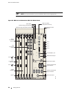
To install the
line modules in a redundancy group:
1. Install the sp
are line module in the lowest-numbered slot of the redundancy
group.
2. Install the o
ther line modules in the remaining slots. (See “Installing Line and
I/O Modu les” on page 44.)
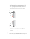
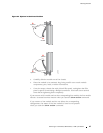
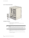
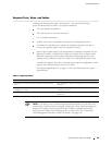
Installing the Redundancy Midplane
To install the redundancy midplane in a redundan cy group:
48 Installing Components for Line Module Redundancy