


ERX 8.0.x Hardware Guide
NOTE: We recommend that you use shielded cables where appropriate.
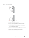
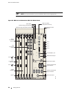
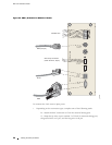
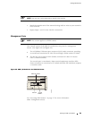
Figure 23: ERX Ports and Connectors (ERX-14xx Model Shown)
A
T
G
R
T1 100 OHM
CLOCK IN
B
T
G
R
E1 75 OHM
CLOCK IN
+
-
+
-
+
-
ALARMSEXTERNAL TIMINGCONSOLE
|
ON
O
OFF
|
ON
O
OFF
THIS PRODUCT IS EQUIPPED WITH
TWO POWER FEEDS. DISCONNECT
BOTH FEEDS PRIOR TO SERVICE.
POWER A POWER B
POWER A POWER B
-48VDC -48VDCRTN RTN
-48VDC RTN -48VDC RTN
WARNING!
NO OPERATOR ACCESSIBLE
COMPONENTS. AUTHORIZED
SERVICE PERSONNEL ONLY.
!
CT3
I/O
CT3
I/O
OC3
I/O
OC3-4
I/O
SINGLE
MODE
OC3-4
I/O
SINGLE
MODE
FE-8
I/O
MINOR
MAJOR
CRITICAL
OC3
I/O module
(slot 13)
10/100
BASE T
RS-232
g013749
FE-8 I/O module
(slot 5)
SRP I/O module
(slot positions 6 and 7)
Alarm leads
External timing ports (Europe)
External timing ports (North America)
10/100 BASE T port
RS-232 terminal port
Power input module
Power A and Power B
on/off switches
Power A and Power B
input connectors
Ground terminals
Port 0
RX
TX
Port 1
RX
TX
Blank
faceplate
Ejector
OC3-4
I/O module
(slot 12)
CT3
I/O module
(slot 9)
Port 0
Port 1
Port 2
Port 3
54 Cabling Overview