


Cabling ERX Routers
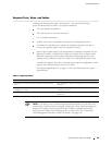
Required Tools, Wires, and Cables
Cabling your s ystem takes only a few m in utes. You need t he following
items and thos
e listed in Table 7 for proper installation:
1/8–inch flat
head screwdriver
3/8–inch wren
ch or 3/8–inch nut-driver
No. 2 Phillips
screwdriver
Ground wires—
We recommend a minimum of 10-AWG ground wire.
#10 (ERX-7xx a
nd ERX-14xx models) or #8 (ERX-310 router) kep nut to
connect the ground (earth) wire to the ground terminal.
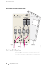
Power input module wiring—We recommend a minimum of 8-AWG wire for
ERX-14xx models, 12-AWG wire for ERX-7xx models, and 14-AWG wire for
ERX-310 rout
ers (DC model) with a dual stud terminal lug with 5/8–inch
spacing. For the ERX-310 router AC model, use a standard IEC power cord.
Consider the distance from the connection point and the configuration of the
system when determining the size of wire used.
See “System Specifications” o n page 119 for more information o n router
specificat
ions.
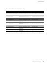
Table 7: Req
uired Cables
Connection Port and Cable Used
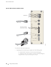
Management connection between SRP I/O module and the
LAN
One 10/100Base-T Ethernet management port with an RJ-45
connector
Management connection between SRP I/O module and a
managemen
tconsole
OneRS-232portwithaDB-9connectorforVT100
managemen
t access
Direct connections to I/O modules See the ERX Module Guide for specific I/O module connector
information
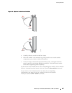
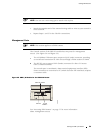
NOTE: If you plan to use a cable-management bracket (ERX-7xx and ERX-14xx
models only), install it before you begin cabling your router. Cable-management
brackets are helpful to keep network interface cables untangled a nd orderly
and to prevent cables from hin dering access to other slots. See “Installing a
Cable-Mana gement Bracket on ERX-7xx Models” on page 100.
Required Tools, Wires, and Cables 55