


ERX 8.0.x Hardware Guide
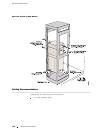
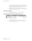
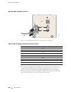
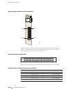
Figure 52: SRP I/O Module Serial Port
CONSOLE
10/100
BASE T
RS-232
DB-9
PIN 1
PIN 9
g013771
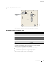
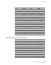
Table19liststhepinoutfortheserialcable’sRS-232connector.
Table 19: SRP I/O Module—RS-232 Serial Connector Pinout
Pin Signal
1DCD
2
RXD
3TXD
4
DTR
5GND
6DSR
7RTS
8CTS
9RNG
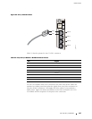
After you have configured an IP address on the system, you can connect using
a host running Telnet over the 10/100Base-T Ethernet port on the SRP I/O
module. The router sh ip s with a straight-through cabl e having a male RJ-45
Ethernet connector on each end. Figure 53 shows the location of the Ethernet
port and the sequence of the pins in the RJ-45 connector.
144 SRP I/O Module