


ERX 8.0.x Hardware Guide
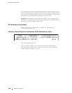
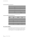
Table 21: DB-9—RJ-45 Crossover Adapter Pinout
DB-9 Pin Signal RJ-45 Pin
1DCD1
2
RXD
3
3TXD2
4
DTR 6
5GND5
6DSR
4
7RTS8
8CTS7
9RNG
no connect
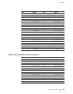
Table 22 lists the p inout for the straight-through adapt er.
Table 22: DB-9—RJ-45 Straight-Through Adapter Pinout
DB-9 Pin
RS-232 Signal
Name RJ-45 Pin
Ethernet Signal
Name
1DCD1TX+
2
RXD
2TX–
3TXD3
RX +
4
DTR
4
no connect
5
GND (signal)
5
no connect
6DSR6
RX –
7RTS7
no connect
8CTS8
no connect
9RNG
no connect none
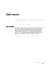
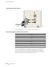
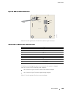
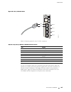
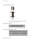
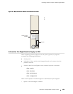
CT1 and CE1 I/O Modules
CT1 I/O modules have 24 RJ-48C female connectors. CE1 I/O modules have either
20 RJ-48C female con nectors or two 25-pair female Telco connectors. F igu re 54
shows the location of the ports on a CT1 I/O module and the sequence of the pins
in the RJ-48C connector. CE1 I/O modules equipped with RJ-48C connectors have
the same configuration as CT1 I/O modules equipped with RJ-48C connectors.
146 CT1 and CE1 I/O Modules