


ERX Overview
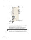
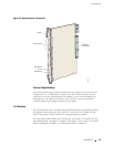
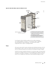
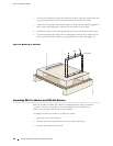
Figure 12: Data Flow When a Spare Line Module Is Active
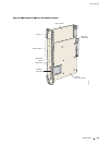
Midplane
Redundancy
midplane
Spare line module
Primary line module
Redundancy
I/O module
Primary
I/O module
1. A packet arrives at the primary I/O module.
2. The packet passes along the redundancy
midplane from the primary I/O module to
the redundancy I/O module.
3. The packet passes from the redundancy
I/O module to the spare line module.
4. The spare line module processes the packet.
g013738
For information about installing modu les for line modu le redundancy,
see “In
stalling Modules” o n page 35 . For informati on about c onfiguring
and managing SRP module redundancy, see JUNOSe System Basics
Configuration Guide, Chapter 6, Managing Modules.
Power
All E-series routers provide a power architecture that distributes redundant –48 VDC
feeds through the router to each line module, SRP module, and fan module where
DC-to
-DC converters provide local conversion to the required secondary voltages.
The ER
X-310 router is available with either DC or AC power inputs. The AC-powered
version can be configured with one or two hot-swappable power supplies for optional
redundancy. (See Figure 5 and Figure 6.) The power supplies convert AC power to
inte
rnal –48 V redundant DC feeds that are then distributed through the router.
Redundancy Features 19