


ERX Overview
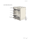
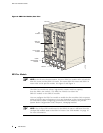
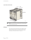
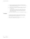
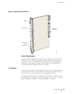
Figure 6: ERX-310 Router, Rear View (AC Model)
SRP I/O
module
I/O module
Grounding posts
ESD grounding jack
AC power inputs and
switches A and B
g013732
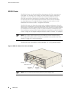
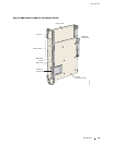
Figure 7: E
RX-310 Router, Rear View (DC Model)
DC power inputs
and switches A and B
SRP I/O
module
I/O
module
Grounding posts
ESD grounding jack
g013733
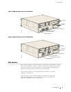
ERX Mod
ules
Each sy
stem supports an SRP module and a selection of line modules. You can
use any line m odule for access or uplink . Access line modules receive traffic
from low-speed circuits, and the system routes the traffic onto higher-speed
uplin
k line modules and then to the core of the network.
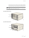
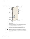
Each m
oduleconnectstoacorrespondingI/Omoduleviaapassive
midplane. See Figure 8.
The front panel of each module contains a collection of status LEDs
(light-emitting diodes). For information about h ow to interpret th e
LEDs,
see “Troubleshooting” on page 103.
ERX Modules 9