


ERX 8.0.x Hardware Guide
Cabling the SRP I/O Module
Before powering up the router, you must set up a management console. The
console enabl
es yo u to communicate with your system during the power-up process
and to manage your system using the command-line interface (CLI).
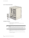
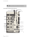
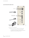
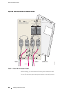
When connecting a console directly to the SRP I/O module, use a cable appropriate
foryourterminalconnector.ThecablemusthaveafemaleDB-9connectortoattach
to the RS-232
port on the SRP I/O mod ul e. See Figure 24 and Figure 25.
The console p
ort is considered a data term in al equ ip m en t interface
(DTE). Direct connection to a terminal or PC (which also have DTE
interfaces) requires a crossover cable.
NOTE: The alar
m function on the SRP I/O module is currently not implemente d.
Only ERX-7xx and ERX-14xx models have external timing ports and alarm leads
located on th
e SRP I/O module. All ERX routers have console ports located on
the SRP I/O module. See Table 8 for details on each component.
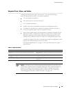
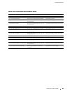
Table 8: SRP I/O Ports
Port Description
Alarm leads (ERX-7xx and ERX-14xx models
only)
Six terminal blocks for external alarm
contacts; use a minimum 26-AWG for each
(currently not implemented)
External timing ports (ERX-7xx and ERX-14xx
models only)
Two 3-pin wire-wrap posts for US
external clock sources; primary (A)
and seconda
ry (B)
Two BNC connectors for E1 clock
sources; pr
imary (A) and secondary (B)
Management console ports One 10/100Base-T Ethernet
management port with an RJ-45
connector
One RS-232 console port with a DB-9
connector for VT100 management
access
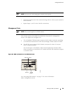
External Timing Ports
NOTE: This section applies to ERX-7xx and ERX-14xx models only. The ERX-310
router does not support external timing.
56 Cabling the SRP I/O Module