


ERX 8.0.x Hardware Guide
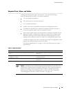
Connecting to the Network
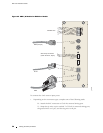
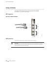
To connect the router to the network:
1. Insert an Ethernet cable (RJ-45) connector into the 10/100Base-T (RJ-45) port
on the SRP I/O m
odule until it clicks into place.
2. Connect the other end of the cable to the appropriate Ethernet network for
an ou t-of-b an
dconnection.
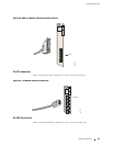
Connecting t
o a Console Terminal
When you conn
ect a console directly to the router SRP I/O module, use a cable
appropriate for your terminal connector. The cable must have a female DB-9
connector to attach to the R S-232 port on the SRP I/O module.
To connect the console to the SRP I/O module:
1. InsertthefemaleDB-9connectorintotheRS-232port,andtightenthescrews.
2. Connect the other end of the cable to your terminal’s serial port (VT100/ANSI).
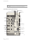
Cabling the Router for Power
After you have correctly cabled the modu les and I/O modules, you
must attach grounding and electrical wires before you attempt system
power-up. T
hree main tasks are involved:
1. Switch all r
outer power switches to OFF.
CAUTION: Sw
itches may have inadvertently flipped to ON during s hipping and
installation.
2. Connect the grounding wires to the chassis.
WARNING: Always connect the grounding wires first (before connecting the power
cables) and disconnect them last when installing or servicing the router.
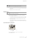
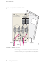
3. Connect the power cables (AC or DC) to the power input modules.
See “System
Specifications” on page 119 for the power requirements for ERX
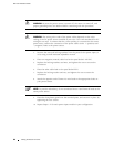
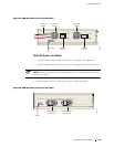
routers. Table 9 identifies the power input mod ule cabling requirements, an d
Figure 26 sh ows the main components of a power input module.
60 Cabling the Router for Power