


ERX 8.0.x Hardware Guide
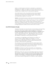
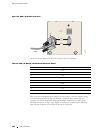
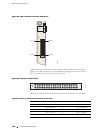
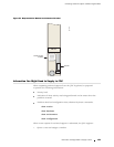
Figure 55: CE1 I/O Module with Telco Connectors
PIN 25
PIN 1
CE1
I/O
PIN 50
PIN 26
0-9
g013774
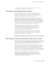
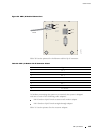
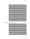
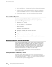
Figure 5
6 shows the location of the 20 pairs of BNC connectors on a balun
panel. The cables from the CE1 I/O module are plugged into the two 50-pin
Telco connectors on the other side of the panel.
Figure 56: Twenty-Port Balun Panel
TX
RX
PORT
1021 3456789 111213141516171819
g013775
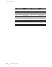
Table24andTable25listthepinoutsfortheTelcoconnectorsoneachcable.
Table 24: Pinout of 50-Pin Telco Connector to Ports 0–9
Pin Signal Pin Signal
1 Port 0 RX TIP 26 Port 0 RX RING
2 Port 0 TX TIP 27 Port 0 TX RING
3 Port 1 RX TIP 28 Port 1 RX RING
4
Port 1 TX TIP 29 Port 1 TX RING
5 Port 2 RX TIP 30 Port 2 RX RING
148 CT1 and CE1 I/O Modules