


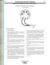

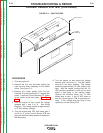


B
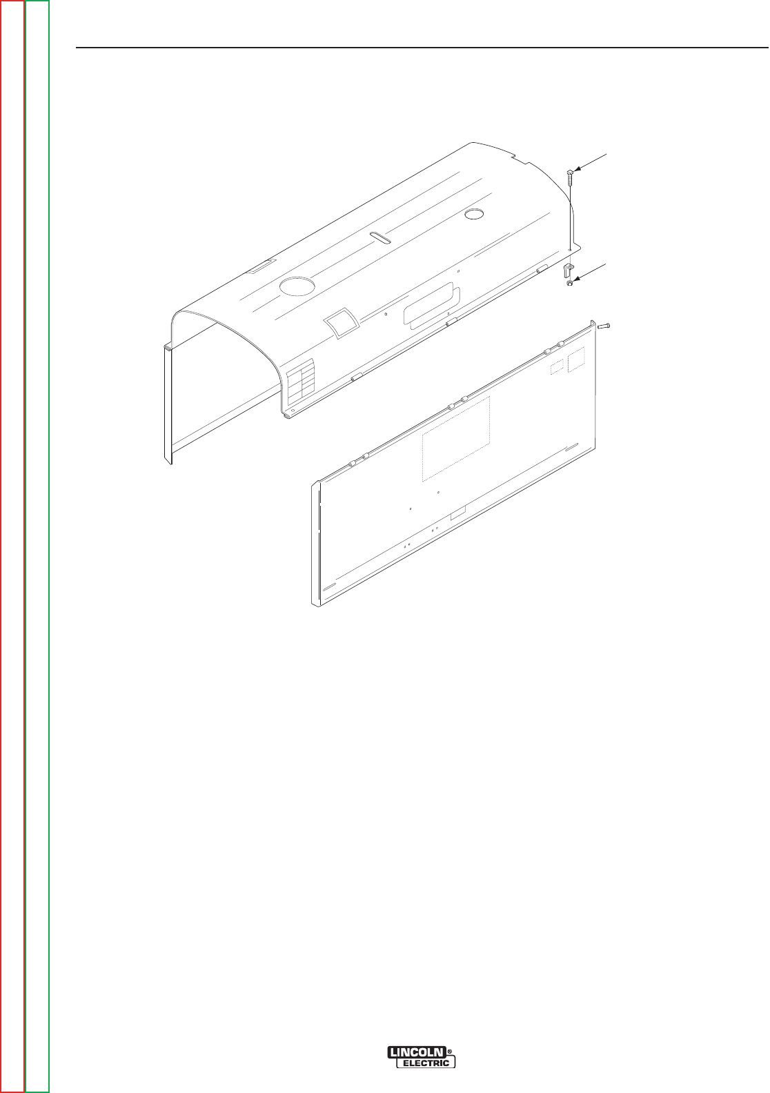
OLT / NUT (4)
“
L”DOOR
H
OOKS (4)
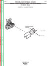
FIGURE F.11 - CASE COVERS
CURRENT SENSOR PCB TEST (CONTINUED)
PROCEDURE
1. Turn the engine off.
2. Remove the four nuts and bolts holding the
case top and doors assembly to the welder
frame. See Figure F.11.
3. Remove the rubber gasket from the top.
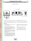
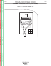
Carefully lift up and remove the “L” shaped door
hooks. Locate the Current Sensing P.C. Board
on the inside of the front panel. See Figure
F.12.
4. Turn the engine on and record the voltage
between pins 1 and 2 of J1. See Wiring
Diagram. This voltage should be approximate-
ly 12 VDC (battery voltage).
5. Turn the engine back OFF and locate pins 4
and 2 on J1 of the Current Sensor PCB and
place the Volt/Ohm Meter leads into the back of
the molex plug.
6. Turn the engine on and record the voltage
between pins 4 and 2 on J1. The Idler Switch
must be in the “Auto” position. This voltage
should be approximately 12 VDC (battery volt-
age). With the engine running load the 115
VDC auxiliary receptacle or strike an arc using
either a load bank or the welding leads.
Observe the Volt/Ohm Meter; the 12 VDC
should drop to zero. If the 12 VDC drops to
zero the current sensor PCB is operating cor-
rectly. If the voltage does not drop to zero
replace the current sensor PCB.
TROUBLESHOOTING & REPAIR
F-34 F-34
PIPELINER® 200
Return to Section TOC Return to Section TOC Return to Section TOC Return to Section TOC
Return to Master TOC Return to Master TOC Return to Master TOC Return to Master TOC