


OPERATION
BBB-4 BBB-4
PIPELINER® 200G
CONTROL OF WELDING CURRENT
DO NOT TURN THE “CURRENT RANGE SELEC-
TOR” WHILE WELDING because the current may
arc between the contacts and damage the switch.
------------------------------------------------------------------------
The “Current Range Selector” provides five overlap-
ping current ranges. The “Fine Current Adjustment”
adjusts the current from minimum to maximum within
each range. Open circuit voltage is also controlled by
the “Fine Current Adjustment” permitting control of the
arc characteristics.
A high open circuit voltage setting provides the soft
“buttering” arc with the best resistance to pop-outs pre-
ferred for most welding. To get this characteristic, set
the “Current Range Selector” to the lowest setting that
still provides the current you need and set the
“Fine
Current Adjustment” near maximum. For example: to obtain
175 amps and a soft arc, set the “Current Range Selector” to
the 190-120 position and then adjust the “Fine Current
Adjustment” for 175
amps.
When a forceful “digging” arc is required, usually for
vertical and overhead welding, use a higher “Current
Range Selector” setting and lower open circuit voltage.
For example: to obtain 175 amps and a forceful arc, set
the “Current Range Selector” to the 240-160 position
and the “Fine Current Adjustment” setting to get 175
amps.
DO NOT attempt to set the “Current Range Selector”
between the five points designated on the nameplate.
------------------------------------------------------------------------
These switches have a spring loaded cam which
almost eliminates the possibility of setting this switch
between the designated points.
TBI DEICING SYSTEM
The welder has been designed to allow continuous
year-round operation. Engine coolant is channeled
through the TBI housing to prevent the build up of ice
on the TBI throat around the throttle plate. the elec-
tronic controller is programmed to automatically com-
pensate for the build up of ice on the throttle plate.
There will be no noticeable change in the operation of
the welder should icing develop. On start-up, there is a
possibility for the engine to overspeed (to a maximum
of 2000 RPM) for up to 10 seconds after throttle body
icing conditions have occurred. The electronic gover-
nor will correct itself for the new operating conditions
and normal operation will resume.
IDLER OPERATION
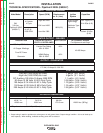
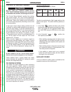
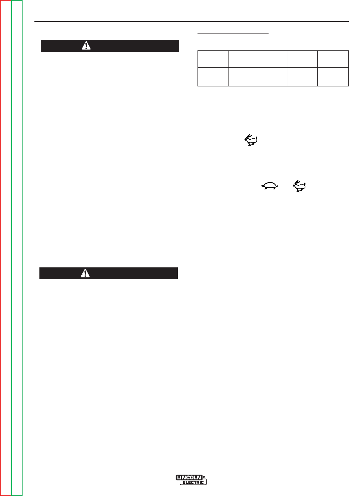
The operating speeds are as follows:
The idler is controlled by the “Idler” toggle switch on the
welder control panel. The switch has two positions as
follows:
1. In the “High” position, the idler is off, and the
engine runs at the high speed controlled by the gov-
ernor. This speed can be adjusted between 1500
and 1600 RPM using the RPM dial on the output
rail.
2. In the “Automatic” / position, the
idler operates as follows:
• When welding or drawing power for lights or tools
(approximately 100-150 watts minimum) from the
receptacle, the engine operates at the speed, set
by the RPM dial.
• When welding ceases or the power load is turned
off, a preset time delay of 10 seconds starts. This
time delay cannot be adjusted.
• If the welding or power load is not re-started
before the end of the time delay, the idler reduces
the engine to low idle speed.
AUXILIARY POWER
1.75 kw of 120V DC auxiliary power is available at the
receptacle located on the control panel.
CAUTION
CAUTION
ORDERING
INFO.
ENGINE FULL
LOAD
HIGH
IDLE
LOW
IDLE
K6090-7 GM 3.0L 1600-
1500
1600-
1500
1360
Return to Section TOC Return to Section TOC Return to Section TOC Return to Section TOC
Return to Master TOC Return to Master TOC Return to Master TOC Return to Master TOC