


MAIN GENERATOR FRAME REMOVAL AND REPLACEMENT PROCEDURE
(CONTINUED)
TROUBLESHOOTING & REPAIR
F-57 F-57
PIPELINER® 200
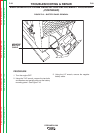
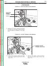
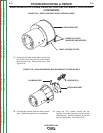
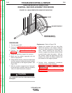
FIGURE F.24 – BRUSH BRACKET WRAP-AROUND COVER
BRUSH BRACKET
WRAP- AROUND COVER
REMOVE (2) NUTS,
WASHERS, AND SCREWS
27. Using the slot head screw driver, remove the
two screws and nuts from the brush bracket
wrap-around cover. Remove the cover. See
Figure F.24.
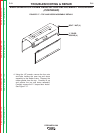
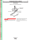
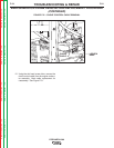
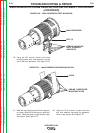
FIGURE F.25 – MAIN GENERATOR BRUSH BRACKET CLAMPING BOLT
BRUSHES (8)
CLAMPING BOLT
BRUSH BRACKET
28. Lift the eight brushes from the main commu-
tator. Note their positions for reassembly.
29. Using the 7/16” wrench, loosen (do not
remove) the main generator brush bracket
clamping bolt. Note the position of the drill
spot for reassembly. See Figure F.25.
Return to Section TOC Return to Section TOC Return to Section TOC Return to Section TOC
Return to Master TOC Return to Master TOC Return to Master TOC Return to Master TOC