


DC EXCITER TEST (CONTINUED)
TROUBLESHOOTING & REPAIR
F-15 F-15
PIPELINER® 200
EXITER
COVER
W
ARRANTY
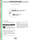
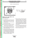
CHECK VOLTAGE
AT BRUSH
HOLDERS HERE
(RIGHT SIDE IS +)
+
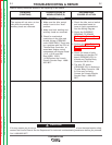
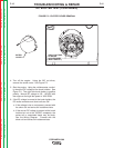
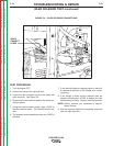
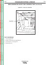
FIGURE F.2 – EXCITER COVER REMOVAL
4. Turn off the engine. Using the 3/8” nut driver,
remove the exciter cover. See Figure F.2.
5. Start the engine. Using the volt/ohmmeter, careful-
ly check the DC voltage at the brush holders. See
Figure F.2. The right side brush holder is positive
polarity. Normal DC voltage is 125 - 135VDC with
the engine at the high idle speed of 1600 RPM.
6. If the DC voltage is normal at the brush holders, the
DC exciter armature and shunt coils are OK.
a. If the voltage is low or not present, proceed with
the shunt coil and series coil resistance tests.
b. If the correct DC voltage is present at the brush
holders but not at the 120VDC receptacle, the
series coil or associated leads may be faulty.
See the Wiring Diagram. Proceed with the
shunt coil and series coil resistance tests.
Return to Section TOC Return to Section TOC Return to Section TOC Return to Section TOC
Return to Master TOC Return to Master TOC Return to Master TOC Return to Master TOC