


OPERATION
BB-4 BB-4
ENGINE BREAK-IN
Lincoln Electric selects high quality, heavy-duty indus-
trial engines for the portable welding machines we
offer. While it is normal to see a small amount of
crankcase oil consumption during initial operation,
excessive oil use, wetstacking (oil or tar like substance
at the exhaust port), or excessive smoke is not normal.
Larger machines with a capacity of 350 amperes and
higher, which are operated at low or no-load conditions
for extended periods of time are especially susceptible
to the conditions described above. To accomplish suc-
cessful engine break-in, most diesel-powered equip-
ment needs only to be run at a reasonably heavy load
within the rating of the welder for some period of time
during the engineʼs early life. However, if the welder is
subjected to extensive light loading, occasional moder-
ate to heavy loading of the engine may sometimes be
necessary. Caution must be observed in correctly
loading a diesel/generator unit.
1. Connect the welder output studs to a suitable
resistive load bank. Note that any attempt to short
the output studs by connecting the welding leads
together, direct shorting of the output studs, or
connecting the output leads to a length of steel will
result in catastrophic damage to the generator and
voids the warranty.
2. Set the welder controls for an output current and
voltage within the welder rating and duty cycle.
Note that any attempt to exceed the welder rating
or duty cycle for any period of time will result in
catastrophic damage to the generator and voids
the warranty.
3. Periodically shut off the engine and check the
crankcase oil level.
PIPELINER® 200D PERKINS
WELDER OPERATION
DUTY CYCLE
The NEMA output rating of the Pipeliner® 200D is 200
amperes at 28
(1)
arc volts on a 60% duty cycle. Duty
cycle is based on a ten minute period; thus, the welder
can be loaded at rated output for six minutes out of
every ten minute period.
(1)
The “Lincoln Plus” output rating at 60% duty cycle
is 200 amperes at 40 Volts.
CONTROL OF WELDING CURRENT
DO NOT TURN THE “CURRENT RANGE SELEC-
TOR” WHILE WELDING because the current may
arc between the contacts and damage the switch.
-----------------------------------------------------------------------
The “Current Range Selector” provides five overlap-
ping current ranges. The “Fine Current Adjustment”
adjusts the current from minimum to maximum within
each range. Open circuit voltage is also controlled by
the “Fine Current Adjustment” permitting control of the
arc characteristics.
A high open circuit voltage setting provides the soft
“buttering” arc with the best resistance to pop-outs pre-
ferred for most welding. To get this characteristic, set
the “Current Range Selector” to the lowest setting that
still provides the current you need and set the “Fine
Current Adjustment” near maximum. For example: to
obtain 175 amps and a soft arc, set the “Current Range
Selector” to the 190-120 position and then adjust the
“Fine Current Adjustment” for 175 amps.
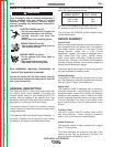
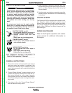
CAUTION
ELECTRIC SHOCK can kill.
• Do not touch electrically live parts or
electrode with skin or wet clothing.
• Insulate yourself from work and ground.
FUMES & GASES can be dangerous.
• Keep your head out of the fumes.
• Use ventilation or exhaust to remove
fumes from breathing zone.
WELDING SPARKS can cause fire or
explosion.
• Keep flammable material away.
ARC RAYS can burn.
• Wear eye, ear, and body protection.
WARNING
Return to Section TOC Return to Section TOC Return to Section TOC Return to Section TOC
Return to Master TOC Return to Master TOC Return to Master TOC Return to Master TOC