


INSTALLATION
A-5 A-5
PRE-OPERATION SERVICE
READ the engine operating and maintenance instruc-
tions supplied with this machine.
OIL
This unit is supplied from the factory with the engine
crankcase filled with a high quality SAE 10W/30 oil.
This oil should be acceptable for most typical ambient
temperatures. Consult the engine operation manual
for specific engine manufacturerʼs recommendations.
Upon receipt of the welder, check the engine dipstick to
be sure the oil is at the “full” mark. DO NOT overfill.
FUEL
Fill the fuel tank with the grade of fuel recommended in
the Engine Operatorʼs manual. Make sure the valve on
the water separator is in the open position.
COOLING SYSTEM
The radiator has been filled at the factory with a 50-50
mixture of ethylene glycol antifreeze and water. Check
the radiator level and add a 50-50 solution as needed
(see engine manual or antifreeze container for alter-
nate antifreeze recommendations).
CAUTION
PIPELINER® 200D KUBOTA
TRAILER (See Accessories Section)
If the user adapts a non-Lincoln trailer, the user must
assume responsibility that the method of attachment
and usage does not result in a safety hazard nor dam-
age the welding equipment. Some of the factors to be
considered are as follows:
1. Design capacity of trailer vs. weight of Lincoln
equipment and likely additional attachments.
2. Proper support of, and attachment to, the base of
the welding equipment so there will be no undue
stress to the framework.
3. Proper placement of the equipment on the trailer to
ensure stability side to side and front to back when
being moved and when standing by itself while
being operated or serviced.
4. Typical conditions of use, i.e., travel speed, rough-
ness of surface on which the trailer will be operat-
ed; environmental conditions, likely maintenance.
5. Conformance with federal, state and local laws.
(1)
(1)
Consult your federal, state and local laws regarding specific
requirements for use on public highways.
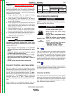
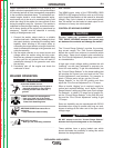
POLARITY CONTROL AND CABLE SIZES
With the engine off, route the electrode and work
cables through the strain relief bracket on the base and
connect to the studs located below the fuel tank mount-
ing rail. (See size recommendations below.) For pos-
itive polarity, connect the electrode cable to the termi-
nal marked “+”. For Negative polarity, connect the
electrode cable to the “-” stud. These connections
should be checked periodically and tightened if neces-
sary.
When welding at a considerable distance from the
welder, be sure you use ample sized welding cables.
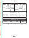
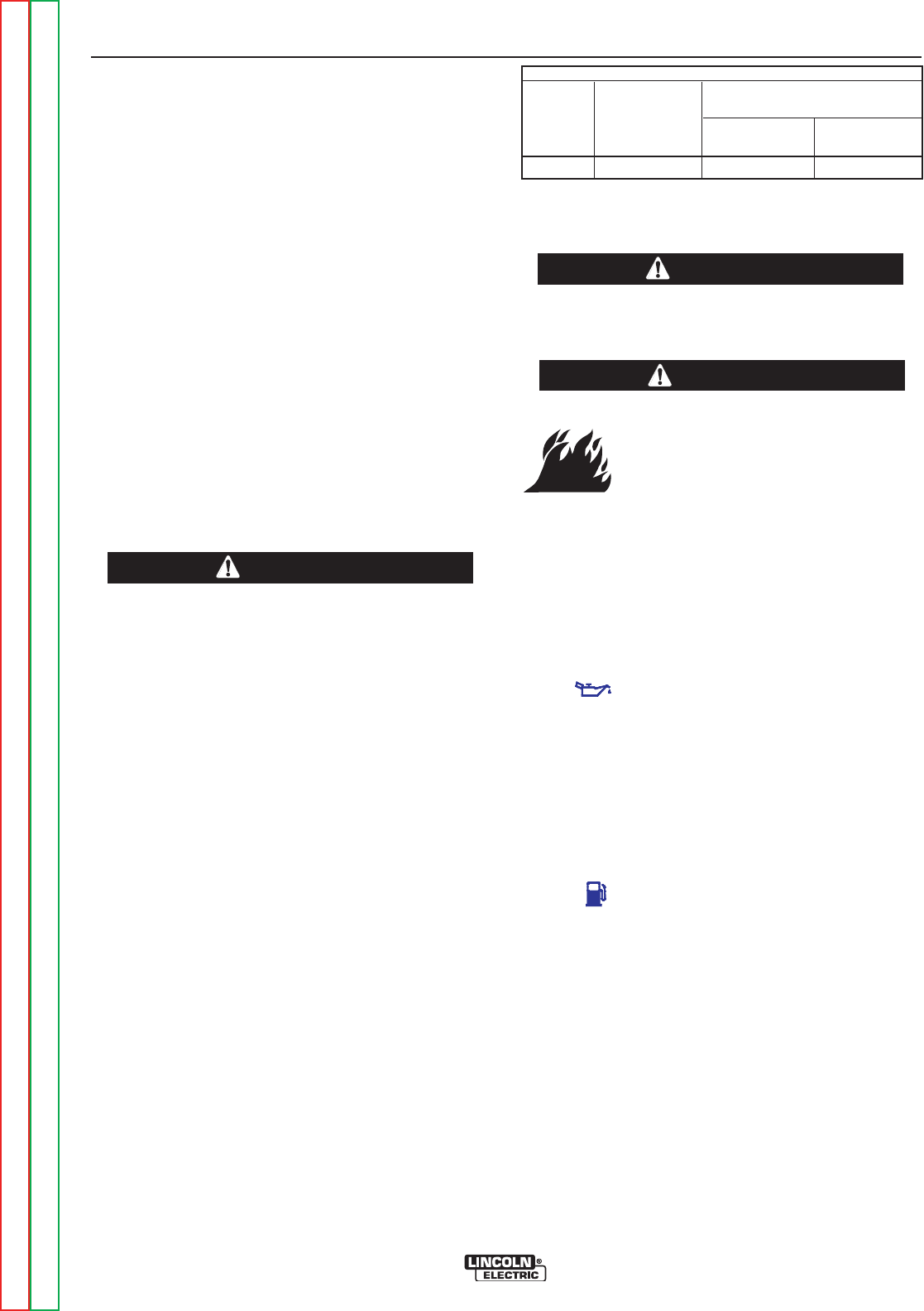
RECOMMENDED COPPER CABLE SIZES
Cables Sizes for Combined Length
of Electrode Plus Work Cable
Amps Duty Cycle Up to 200ft.(61m) 200 to 250ft.
(61 to 76m)
200 60% 1 1/0
VEHICLE MOUNTING
Improperly mounted concentrated loads may
cause unstable vehicle handling and tires or other
components to fail.
• Only transport this Equipment on serviceable
vehicles which are rated and designed for such
loads.
• Distribute, balance and secure loads so vehicle
is stable under conditions of use.
• Do not exceed maximum rated loads for compo-
nents such as suspension, axles and tires.
• Mount equipment base to metal bed or frame of
vehicle.
• Follow vehicle manufactureʼs instructions.
------------------------------------------------------------------------
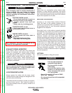
WARNING
• Stop engine while fueling.
• Do not smoke when fueling.
• Keep sparks and flame away
from tank.
• Do not leave unattended while
fueling.
• Wipe up spilled fuel and allow
fumes to clear before starting
engine.
• Do not overfill tank, fuel expan-
sion may cause overflow.
DIESEL FUEL ONLY
------------------------------------------------------------------------
WARNING
DIESEL FUEL
can
cause fire
Return to Section TOC Return to Section TOC Return to Section TOC Return to Section TOC
Return to Master TOC Return to Master TOC Return to Master TOC Return to Master TOC