


THEORY OF OPERATION
E-7 E-7
PIPELINER® 200
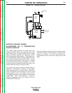
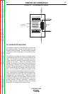
DC GENERATOR MACHINES
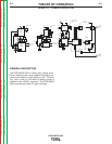
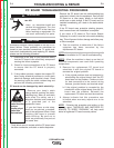
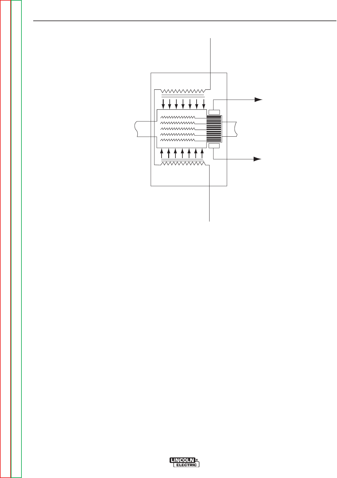
The armature winding of a DC generator is located on
the rotating member. Current is conducted from it by
means of carbon brushes. The field winding is located
in the stator, which is stationary and excited by direct
current.
The armature coil sides are placed at opposite points
on the rotating shaft with the conductors parallel to the
shaft. The armature assembly is normally turned at a
constant speed by a source of mechanical power con-
nected to the shaft. When the armature rotates
through the magnetic field produced by the stationary
field winding, it induces a coil voltage in the armature
winding. The voltage induced in an individual armature
coil is an alternating (AC) voltage, which must be recti-
fied. In a conventional DC generator machine, rectifi-
cation is provided mechanically by means of a commu-
tator. A commutator is a cylinder formed of copper seg-
ments insulated from each other and mounted on, but
insulated from, the rotating shaft. Stationary carbon
brushes held against the commutator surface connect
the armature windings to external terminals. The com-
mutator provides full-wave rectification, transforming
the voltage waveform between brushes and making
available a DC voltage to the external circuit.
FIGURE E.7 — DC GENERATOR THEORY
BRUSH
BRUSH
MAGNETIC FIELD
G
ENERATOR
ARMATURE
MAGNETIC FIELD
SHUNT FIELD WINDINGS
SHUNT FIELD WINDINGS
M
ECHANICAL
COUPLING
ARMATURE
SHAFT
DC CURRENT
DC CURRENT
F
I
E
L
D
C
U
R
R
E
N
T
F
I
E
L
D
C
U
R
R
E
N
T
Return to Section TOC Return to Section TOC Return to Section TOC Return to Section TOC
Return to Master TOC Return to Master TOC Return to Master TOC Return to Master TOC