


TROUBLESHOOTING & REPAIR
F-21 F-21
PIPELINER® 200
MAIN GENERATOR SHUNT FIELD WINDING TEST (continued)
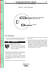
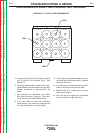
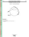
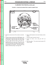
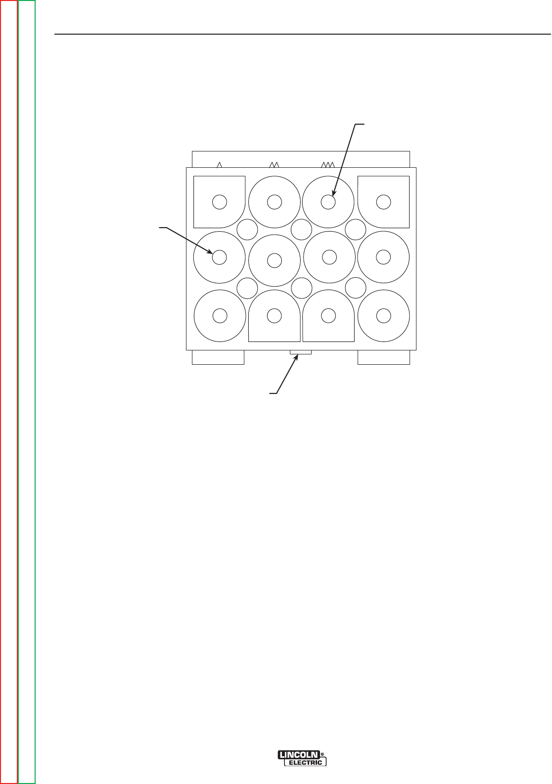
FIGURE F.6 – PLUG P10 PIN ASSIGNMENTS
PIN 3
PIN 5
TAB
5. Locate the blue (U) (pin 3) and the brown (N)
(pin 5) leads in the harness plug. See
Figure F.6.
6. Using the volt/ohmmeter, measure the resis-
tance between the blue and the brown lead.
Normal resistance is approximately 40
ohms.
7. Also measure the resistance from either
lead (blue or brown) to ground. This resis-
tance should be at least 500,000 ohms.
8. If the test does not meet the resistance
specifications, then check the harness plug
for loose connections or shorted leads.
9. If the plug and associated leads are okay,
the shunt field coils may be faulty. Replace
the shunt field coils.
10. If the test does meet the resistance specifi-
cations, the main shunt coils are okay.
11. Replace plug P10, making sure the leads
and plug are secure.
12. After the test and repairs are completed,
close and latch the right side door.
Return to Section TOC Return to Section TOC Return to Section TOC Return to Section TOC
Return to Master TOC Return to Master TOC Return to Master TOC Return to Master TOC