


MAIN GENERATOR FRAME REMOVAL AND REPLACEMENT PROCEDURE
(CONTINUED)
TROUBLESHOOTING & REPAIR
F-53 F-53
PIPELINER® 200
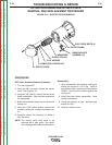
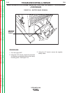
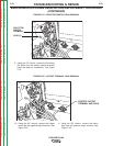
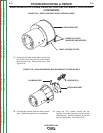
FIGURE F.19 – SELECTOR SWITCH LEAD REMOVAL
SELECTOR
SWITCH
TERMINAL
LEAD (5)
A
C
B
D
E
9. Using the 1/2” wrench, remove the five heavy
flex leads from the selector switch terminals.
Label the leads for reassembly. See Figure
F.19.
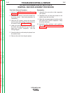
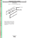
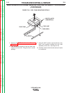
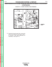
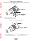
FIGURE F.20 – OUTPUT TERMINAL LEAD REMOVAL
POSITIVE OUTPUT
TERMINAL AND LEAD
A
C
B
D
E
10. Using the 3/4” wrench, remove the copper
strap from the negative output terminal. See
Figure F.20.
11. Using the 3/4” wrench, remove the heavy
lead from the positive output terminal. See
Figure F. 20.
Return to Section TOC Return to Section TOC Return to Section TOC Return to Section TOC
Return to Master TOC Return to Master TOC Return to Master TOC Return to Master TOC