


THEORY OF OPERATION
E-5 E-5
PIPELINER® 200
BATTERY, STARTER, ENGINE
ALTERNATOR, OIL, & TEMPERATURE
SWITCH CIRCUITS
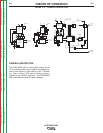
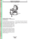
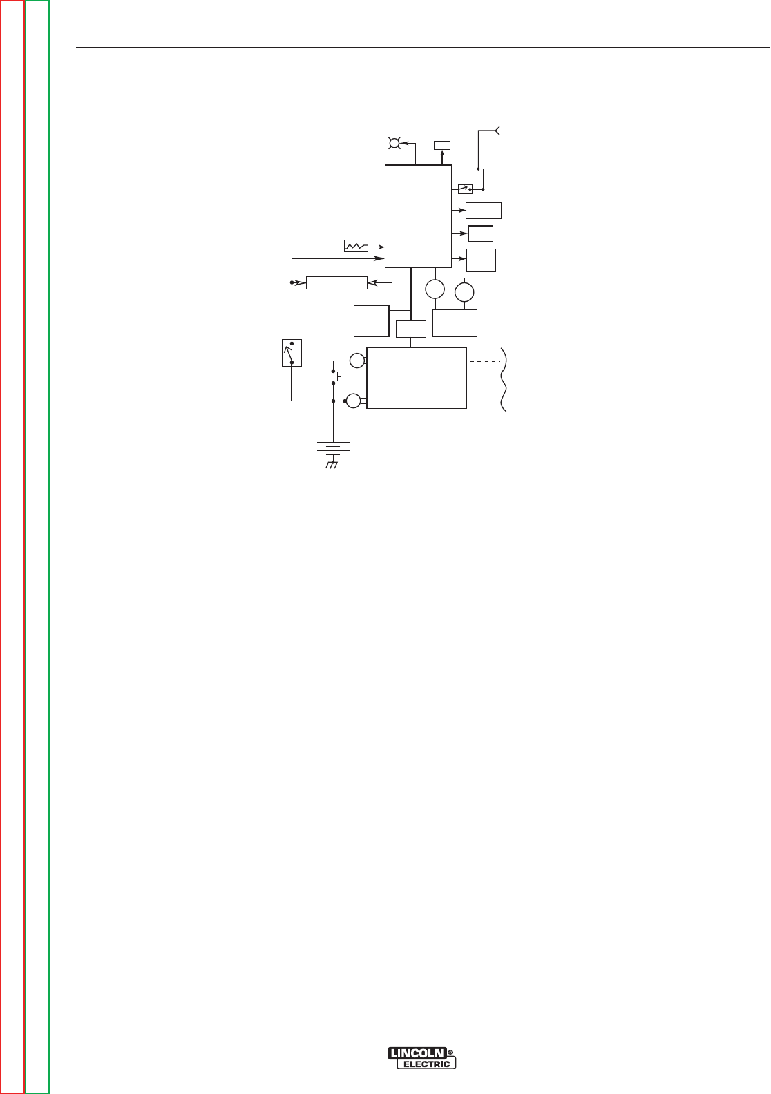
The 12VDC battery powers the starter motor and,
through the ignition switch, the engine ignition circuitry
(gas models only), the engine alternator, the engine
control protection modules and associated circuits.
See the appropriate block diagram. These engine con-
trol and protection modules monitor engine oil pres-
sure, coolant temperature and engine RPM. The sys-
tem shuts the engine down in the event of a sudden
low oil pressure or high coolant temperature. A warn-
ing light on the control panel provides fault codes, or on
some models the engine fault light will glow.
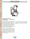
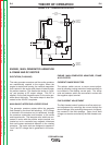
The engine idle control (solenoid, throttle plates or
actuator) is mechanically connected to the engine.
When welding current or auxiliary power (120VDC) is
drawn through the current sensing P.C. board a small
voltage signal is sent to the engine control circuitry.
This signals the engine control circuitry to increase the
engine RPM. This is accomplished in a variety of
methods depending upon the engine and con-
trol/protection being used.
When the welding or auxiliary load is removed a preset
time delay of about 15 seconds starts. After approxi-
mately 15 seconds of “no load” the engine con-
trol/protection circuitry returns the engine to low idle
RPM.
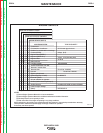
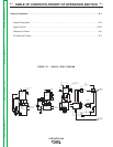
FIGURE E.5 — ENGINE CONTROL
E
NGINE
ALTERNATOR
12 VOLT
B
ATTERY
MAP
SENSOR
WATER
&
A
IR TEMP.
SENSOR
O
IL
P
RESSURE &
WATER TEMP.
SENSOR
THROTTLE
PLATE
MOTOR
FUEL
PUMP
FUEL
INJECTORS
FROM CURRENT
SENSING P.C.BOARD
I
DLER
S
WITCH
E
NGINE
FAILURE
L
AMP
ENGINE
HOUR
METER
RPM
C
ONTROL
ENG.IGNITION
C
IRCUITRY
STARTER
MOTOR
ZENITH
THROTTLE
BODY
C
ONTROLLER
G
.M.
GASOLINE
ENGINE
O
IL
GAUGE
WATER
GAUGE
ENGINE
IGNITION
S
WITCH
COUPLEDTO
G
ENERATOR
Return to Section TOC Return to Section TOC Return to Section TOC Return to Section TOC
Return to Master TOC Return to Master TOC Return to Master TOC Return to Master TOC