


MAIN GENERATOR FRAME REMOVAL AND REPLACEMENT PROCEDURE
(CONTINUED)
TROUBLESHOOTING & REPAIR
F-59 F-59
PIPELINER® 200
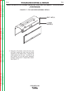
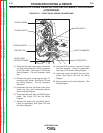
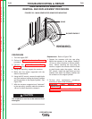
33. Using the rope sling and pry bars, carefully
lift and “wiggle” the generator frame away
from the engine and armature assembly. Be
careful to support the generator frame as
you remove it.
NOTE: The exciter frame is also removed with
the main generator frame.
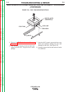
Reassembly: Refer to Figures F.26 & F.27 as
needed.
1. Using the rope sling, carefully lift and “wiggle”
the generator frame onto the engine and
armature assembly. Be careful to support the
generator frame as you position it.
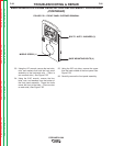
2. Using the 9/16” wrench, install the bolts and
lock washers mounting the generator frame to
the engine. Using the 3/4” wrench, install the
frame mounting bolts, nuts, and washers to
the feet of the main generator. Check air gap
– min. .035” for main generator.
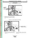
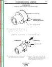
3. Using the 7/16” wrench, tighten the main gen-
erator brush bracket clamping bolt. Note the
position of the drill spot.
4. Install the eight brushes against the main
commutator. Observe the positions you noted
during disassembly.
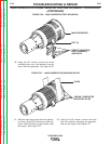
5. Using the slot head screw driver, install the
brush bracket wrap-around cover with two
nuts and screws.
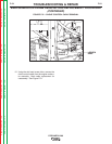
6. Carefully set the front panel assembly into
position. Using the 3/8” nut driver, install the
screw for the lower middle of the front panel.
Using the 9/16” wrench, install the four bolts,
nuts, and washers for the bottom of the front
panel assembly. Then install the two bolts,
nuts, and washers that hold the front panel
assembly to the horizontal rails.
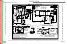
7. Reconnect all leads previously removed. See
the Wiring Diagram.
8. Carefully position the fuel tank to the mount-
ing rails. Using the 9/16” wrench, install the
four nuts, bolts, and washers holding the fuel
tank assembly to the rails. Remove the plug
from the fuel line and attach it to the fuel bowl.
9. Perform the DC Exciter Armature
Reassembly Procedure.
10. Carefully set the top and doors assembly
into place. Install the “L” shaped door hooks.
Using the 1/2” wrench, install the four nuts
and bolts holding the case top and doors
assembly to the welder frame. Install the
rubber gasket to the top.
11. Using the 1/2” wrench, install the negative
battery cable. Slide the battery mounting
panel back into place and, using the 7/16”
wrench, install the two bolts and washers
that secure the panel.
Return to Section TOC Return to Section TOC Return to Section TOC Return to Section TOC
Return to Master TOC Return to Master TOC Return to Master TOC Return to Master TOC