


TROUBLESHOOTING & REPAIR
F-18 F-18
PIPELINER® 200
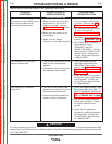
IDLER SOLENOID TEST (continued)
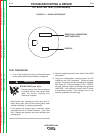
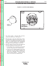
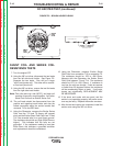
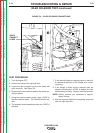
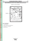
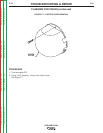
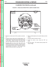
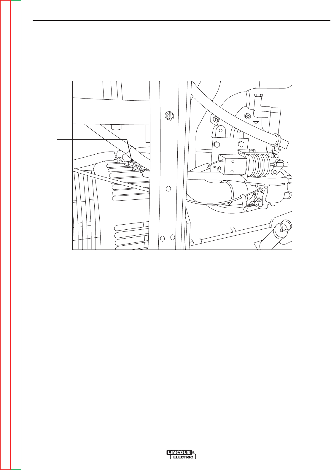
FIGURE F.4 – IDLER SOLENOID CONNECTIONS
QUICK
CONNECT
LEADS
TEST PROCEDURE
1. Turn the engine OFF.
2. Unlatch and secure the right side door.
3. Locate the idler solenoid and the two leads with
quick connects. See Figure F.4.
4. Disconnect the two solenoid leads at the quick con-
nection splices.
5. Using the external power supply, apply 12VDC to
the idler solenoid leads. The solenoid should acti-
vate.
6. The solenoid should deactivate when the 12VDC is
removed.
7. If the solenoid does not operate properly, check for
a mechanical restriction in the linkage or for a miss-
ing spring.
8. If the linkage is intact and the solenoid does not
operate correctly when 12VDC is applied, the idler
solenoid may be faulty. Replace the idler solenoid.
NOTE: Normal solenoid coil resistance is approxi-
mately 9 ohms.
9. After the test and repairs are completed, close and
latch the right side door.
Return to Section TOC Return to Section TOC Return to Section TOC Return to Section TOC
Return to Master TOC Return to Master TOC Return to Master TOC Return to Master TOC