


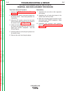
MAIN GENERATOR FRAME REMOVAL AND REPLACEMENT PROCEDURE
(CONTINUED)
TROUBLESHOOTING & REPAIR
F-55 F-55
PIPELINER® 200
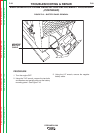
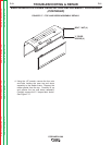
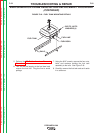
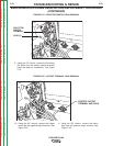
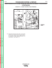
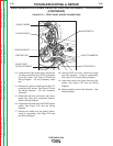
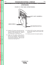
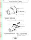
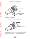
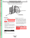
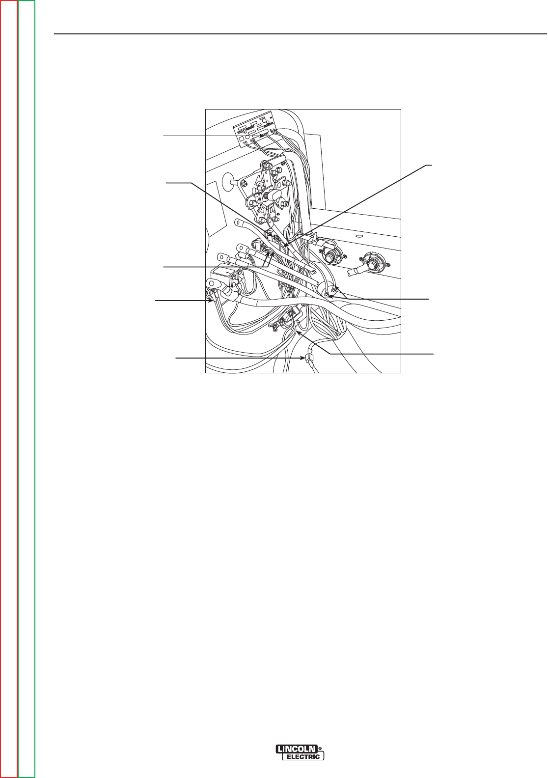
FIGURE F.22 – FRONT PANEL WIRING CONNECTIONS
A
C
B
D
E
IDLER SWITCH
LEADS TO AMMETER
DC RECEPTACLE
IDLER PC BOARD
TO IDLER SWITCH
IGNITION SWITCH
START BUTTON
SHUNT LEADS
QUICK DISCONNECT
13. Using the slot head screw driver, remove the
red lead connecting the 115VDC receptacle
to the DC exciter. See Figure F.22 and the
Wiring Diagram. Cut any necessary cable
ties.
14. Remove the leads connecting the idler PC
board to the DC exciter. See Figure F.22 and
the Wiring Diagram. Cut any necessary
cable ties.
15. Disconnect the blue and brown main shunt
leads from their quick disconnect splices.
See the Wiring Diagram.
16. Disconnect the leads from the START button
switch. See Figure F.22 and the Wiring
Diagram.
17. Remove the leads from the ignition switch.
Label for reassembly. See Figure F.22 and
the Wiring Diagram.
18. Using the 3/8” nut driver, remove the leads
from the ammeter. Label for reassembly.
See Figure F.22 and the Wiring Diagram.
19. Label and remove the leads from the idler
switch. See Figure F.22 and the Wiring
Diagram.
20. Remove leads from the Idler Solenoid. See
Wiring Diagram.
Return to Section TOC Return to Section TOC Return to Section TOC Return to Section TOC
Return to Master TOC Return to Master TOC Return to Master TOC Return to Master TOC