


INSTALLATION
AAA-4 AAA-4
PIPELINER® 200G
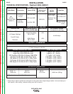
POLARITY CONTROL AND CABLE SIZES
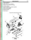
With the engine off, route the electrode and work
cables through the strain relief bracket on the base and
connect to the studs located below the fuel tank mount-
ing rail. (see size recommendations below). For
Positive polarity, connect the electrode cable to the
terminal marked “Positive”. For Negative polarity,
connect the electrode cable to the “Negative” stud.
These connections should be checked periodically and
tightened if necessary.
When welding at a considerable distance from the
welder, be sure you use ample size welding cables.
LIFT BAIL
A lift bail is provided for lifting with a hoist.
TRAILERS (See ACCESSORIES SECTION)
If the user adapts a non-Lincoln trailer, he must
assume responsibility that the method of attachment
and usage does not result in a safety hazard, nor dam-
age the welding equipment. Some of the factors to be
considered are as follows:
1. Design capacity of trailer vs. weight of Lincoln
equipment and likely additional attachments.
2. Proper support of, and attachment to, the base of
the welding equipment so there will be no undue
stress to the framework.
3. Proper placement of the equipment on the trailer to
ensure stability side to side and front to back when
being moved and when standing by itself while
being operated or serviced.
4. Typical conditions of use, i.e., travel speed; rough-
ness of surface on which the trailer will be operat-
ed; environmental conditions; likely maintenance.
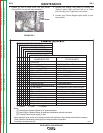
Amps
200
Duty Cycle
60%
Up to 200 ft
(61.0m)
1
200-250 ft
(61.0-72.2m)
1/0
Cable Sizes for Combined
Length of Electrode Plus
Work Cable
RECOMMENDED COPPER CABLE SIZES
5. Conformance with federal, state, and local laws.
(1)
(1)
Consult applicable federal, state, and local laws
regarding specific requirements for use on pub-
lic highways.
VEHICLE MOUNTING
Improperly mounted concentrated loads may
cause unstable vehicle handling and tires or other
components to fail.
• Only transport this Equipment on serviceable vehi-
cles which are rated and designed for such loads.
• Distribute, balance and secure loads so vehicle is
stable under conditions of use.
• Do not exceed maximum rated loads for compo-
nents such as suspension, axles and tires.
• Mount equipment base to metal bed or frame of vehi-
cle.
• Follow vehicle manufactureʼs instructions.
------------------------------------------------------------------------
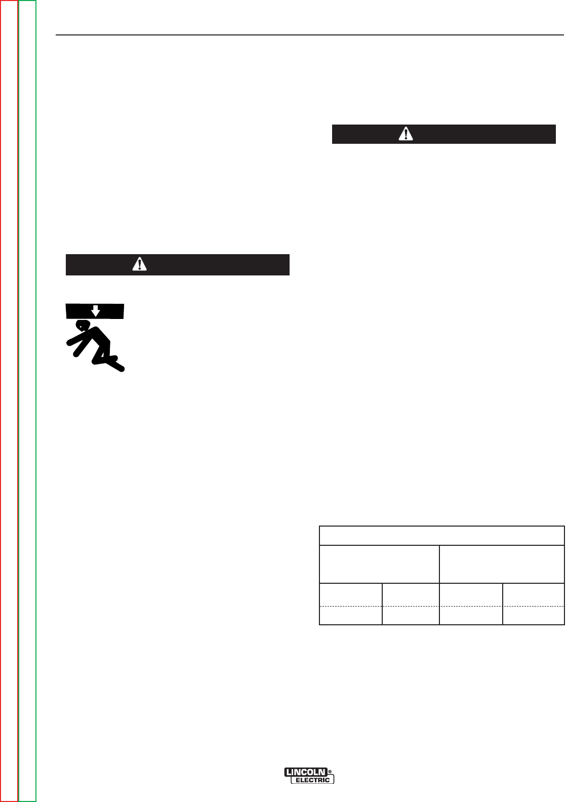
WARNING
ANGLE OF OPERATION
To achieve optimum engine performance the
Pipeliner® 200G should be run in a level position. The
maximum angle of operation for the engine is 60
degrees in a direction to cause the air intake manifold
to be angled up, 45 degrees for the air intake manifold
to be angled down; and 50 degrees for the welder con-
trol panel to be angled up or down. If the engine is to
be operated at an angle, provisions must be made for
checking and maintaining the oil level at the normal
(FULL) oil capacity in the crankcase. When operating
the welder at an angle, the effective fuel capacity will
be slightly less than the specified 15 gallons.
• Lift only with equipment of
adequate lifting capacity.
• Be sure machine is stable
when lifting.
• Do not lift this machine using
lift bale if it is equipped with a
heavy accessory such as trail-
er or gas cylinder.
• Do not lift machine if lift bale
is damaged. Equipment can
be damaged or cause injury.
• Do not operate machine while
suspended from lift bale.
------------------------------------------------------------------------
WARNING
Return to Section TOC Return to Section TOC Return to Section TOC Return to Section TOC
Return to Master TOC Return to Master TOC Return to Master TOC Return to Master TOC