


MAIN GENERATOR FRAME REMOVAL AND REPLACEMENT PROCEDURE
(CONTINUED)
TROUBLESHOOTING & REPAIR
F-58 F-58
PIPELINER® 200
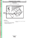
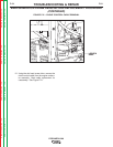
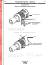
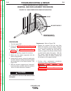
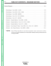
FIGURE F.26 – MAIN GENERATOR FEET MOUNTING
MAIN GENERATOR
REMOVE MOUNTING
NUTS, WASHERS,
AND BOLTS
FEET (2)
30. Using the 3/4” wrench, remove the frame
mounting bolts, nuts, and washers from the
feet of the main generator. See Figure F.26.
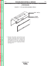
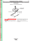
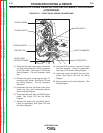
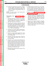
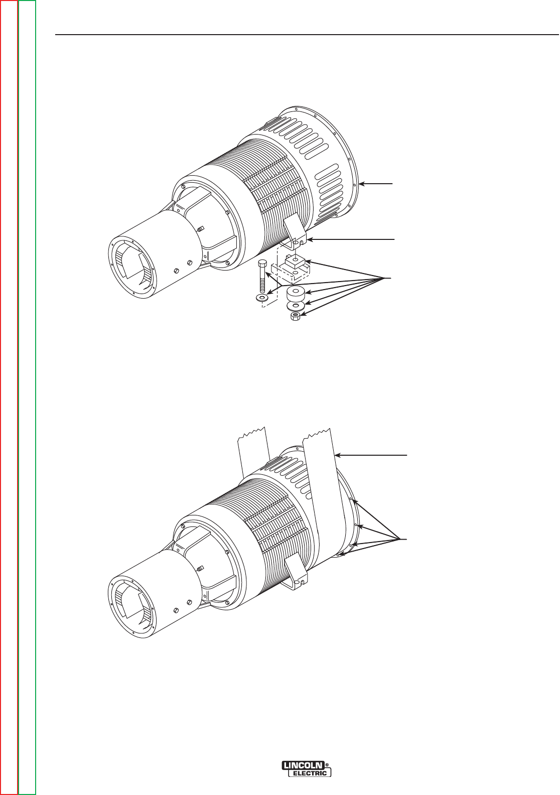
FIGURE F.27 – MAIN GENERATOR ENGINE MOUNTING
ENGINE / GENERATOR
MOUNTING HOLES
SLING
31. With the rope sling around the main genera-
tor frame, carefully lift the frame a small dis-
tance. Slide the wood or steel blocks under
the engine. See Figure F.27.
32. Using the 9/16” wrench, remove the bolts
and lock washers mounting the generator
frame to the engine. See Figure F.27.
Return to Section TOC Return to Section TOC Return to Section TOC Return to Section TOC
Return to Master TOC Return to Master TOC Return to Master TOC Return to Master TOC