


Manual 0-2533 11 INTRODUCTION & DESCRIPTION
SECTION 3:
INTRODUCTION &
DESCRIPTION
3.01 Scope of Manual
The information in this Section is the same information
contained in Section 2 of the Operating Manual. It is sup-
plied here to familiarize the Service Technician with the
capabilities and limitations of the equipment. This infor-
mation will also provide the Service Technician with an
overall understanding of the equipment which will, in
turn, allow proper training of the customer’s operating
personnel.
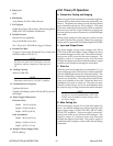
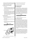
3.02 General Description
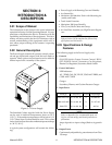
The Power Supply contains all operator controls, electri-
cal and gas inputs and outputs, and the torch leads re-
ceptacle. Many options and accessories can be added to
further improve the versatility of the system.
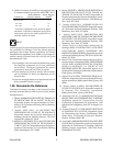
A-00907
Figure 3-1 Power Supply
The Standard Coolant supplied with the Power Supply
can be used in ambient temperatures down to 10° F
(-12° C). If the ambient temperature will be below 10° F
(-12° C) then Super Coolant should be used. This coolant
can be used in areas where the ambient temperature drops
to -34° F (-36° C).
A typical system configuration will contain the follow-
ing:
• Power Supply with Running Gear and Handles
• Arc Starter Box
• Maximizer 300 Machine Torch with Mounting As-
sembly and Leads
• Torch Leads Extension
• Maximizer 300 Spare Parts Kit
• 25 ft (7.6 m) Work Cable and Clamp
• Air Line Filter Assembly (or) High Pressure Regula-
tors
NOTE
Refer to Section 3.05 for complete list of Power Sup-
ply Options and Accessories.
3.03 Specifications & Design
Features
The following apply to the Power Supply only:
1. Controls
ON/OFF Switch, Output Current Control, RUN/
SET/PURGE Switch, Secondary Gas Regulator,
Plasma Gas Regulator, Secondary Mode Switch
2. Control Indicators
LED Indicators:
AC , TEMP, GAS, DC, PILOT, COOLANT PRES, and
COOLANT COND
Gauges:
Secondary, Plasma, and Coolant Pressure Gauges
3. Input Power
Voltage Frequency Phase Amperage
200/220/230 50 or 60 Hz 3 98/89/85
380/415/460 50 or 60 Hz 3 51/47/42
500/575 50 or 60 Hz 3 40/34
NOTE
Refer to Appendix I for recommended input wir-
ing size, current ratings, and circuit protection re-
quirements.
Amps depends on input voltage (Refer to Appendix
I).
4. Output Power
Continuously adjustable by potentiometer from 50 to
150 amps