


Manual 0-2533 41 REPLACEMENT PROCEDURES
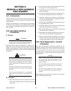
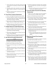
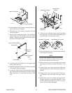
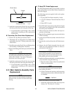
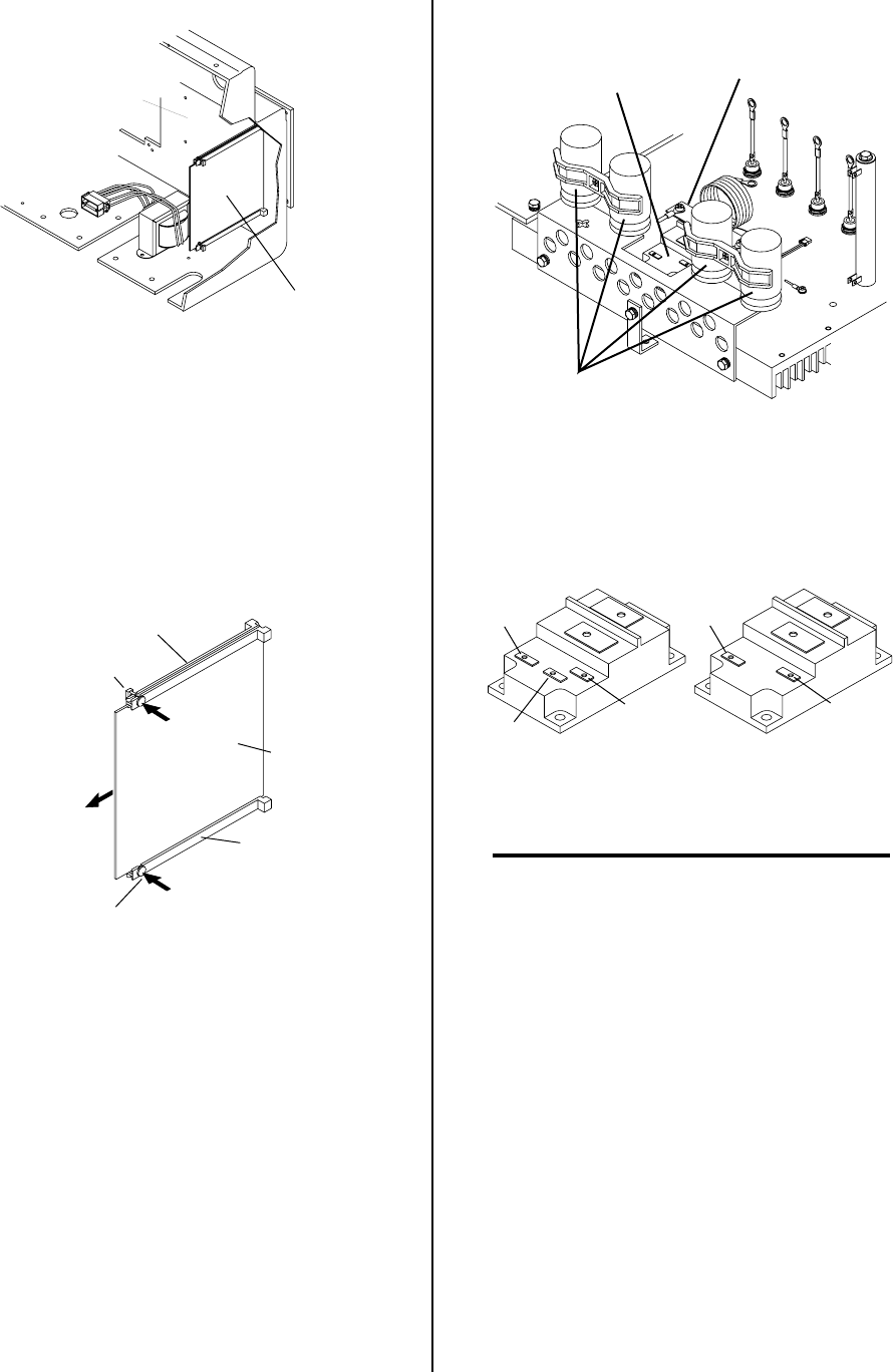
Driver PC Board
Rear of Front Panel
A-01083
5. Note and label the two wiring connectors that con-
nect to the Driver PC Board.
6. Disconnect the two wiring connectors from the
Driver PC Board.
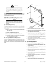
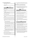
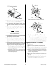
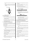
7. Press in the securing tab knob on the PC Board
Guide to release the PC Board from the PC Board
Guides. There is a securing tab on both the upper
and lower PC Board Guides.
Upper PC Board Guide
Lower PC Board
Guide
Securing Tab
Securing Tab
Driver PC
Board
A-01084
8. Carefully pull the PC Board from the guides and
remove from the unit.
9. Install the replacement Driver PC Board Assembly
reversing the above procedure.
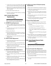
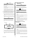
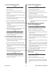
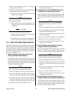
10. Locate the old Switching Transistor (Q1) Assem-
bly on the inside center-left, between the four large
blue capacitors, as viewed from the front of the
unit.
Switching Transistor
Q1
Large Blue
Capacitors
A-01085
Transistor/Coil
Bracket
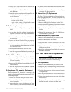
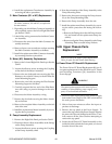
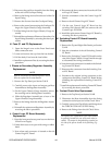
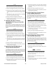
11. There are two different styles of the Switching
Transistor (Q1). The style can be identified by look-
ing at the top of the transistor casing.
Style With 'E' Terminal
Style Without 'E' Terminal
BX
B
E
BX
B
A-01088
12. Note and label the wires connected to the Switch-
ing Transistor Assembly.
NOTE
The older style transistor will have two wire con-
nections to the transistor module and the newer
style will have only one wire connections.
13. Remove the two screws securing the wires to the
Switching Transistor Assembly terminals 'E' and
'B'.
14. Remove the screw that secures the Capacitor
Mounting Bracket to the Switching Transistor As-
sembly
15. Remove the screw that secures the Transistor/
Coil Bracket to the Switching Transistor Assem-
bly.
16. Remove the screw and washer securing the PTC
Resistor Assembly to the Main Heatsink. Move
the PTC Resistor Assembly out of the way to pre-
vent it from becoming damaged.