


SERVICE TROUBLESHOOTING 16 Manual 0-2533
hot soapy water. Remove soap residue by rinsing with
clean hot water. Be sure that all the soap has been
removed and the screen is dry of water before re-in-
stalling in the Internal Filter Assembly.
E. Coolant Level and Conductivity
1. Coolant Level
The coolant level should be checked every day at
the rear panel coolant gauge. If the coolant in the
reservoir is more than 2 inches (50mm) from the
top of the reservoir then add Torch Coolant.
2. Coolant Conductivity
The coolant conductivity LED on the front panel
must be ON for normal operation. If the LED is
OFF then drain the old coolant from the Power
Supply and torch leads and replace with new cool-
ant. Check the condition of the deionizer bag in
the reservoir basket, if the bag is yellowish brown
(straw color) replace the bag.
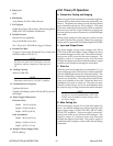
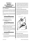
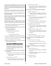
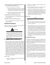
F. Draining Coolant
Remove the old coolant from the Power Supply res-
ervoir per the following procedure:
1. Remove the right side and top panels from the
Power Supply.
2. Disconnect the coolant hose input to the rear panel
filter assembly.
3. Carefully lower the hose out the right side of the
Power Supply and drain the coolant into an ac-
ceptable container.
CAUTION
Handle and dispose of the used coolant per recom-
mended procedures.
Coolant Hose
Coolant Hose
Connection
A-01017
Figure 4-2 Draining Coolant From Reservoir
4. Reconnect the hose to the filter assembly.
5. Install new coolant and deionizer bag.
6. Reinstall the top and right side panels.
4.03 System Theory
A. Circuit Description
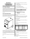
The Merlin 3000 system is designed for mechanized
cutting only and consists of the Merlin 3000 plasma
power supply, the Maximizer 300 Torch, Torch Leads
Extension, and Arc Starter Box. An Optional Remote
Control (RC6010), Standoff Control (SC10 or SC11, see
notes) and Gas Control (GC3000) may be used in vari-
ous combinations. Different interconnect and input/
output (I/O) cables may be used depending on which
options are installed. An Optional Dual Meter, Arc
Hours and Arc Starts Counter, may be included on
the Power Supply front panel.
NOTES
The Standoff Control SC10 must be used with the
Remote Control RC6010.
The Remote Control RC6010 is not used if the
Standoff Control SC11 is used.
B. Input Voltage Selection
The main transformer (T1) has busbar connections to
select one of three input voltage ranges. Each main
transformer secondary has two taps. One secondary
tap is automatically selected by the Voltage Selection
PC board when primary power is applied. If input
voltage is within the lower half of the selected volt-
age range (for example, 380V or 415V in the 380/415/
460V range), the higher voltage taps are selected. If
input voltage is within the upper half of the selected
voltage range (460V in the 380/415/460V range), the
lower voltage taps are selected. This arrangement
provides secondary voltages close to the optimum
levels. When the lower voltage taps are selected a
red indicator, D18, on the Voltage Selection PC Board
will be ON.
The auxiliary voltage taps, 115 VAC and 28 VAC cir-
cuits, are selected directly by relays on the Voltage
Selection PC Board. The fan and pump motors are
supplied by the Motor Control Contactors (MC1 and
MC2). MC1 is for the high voltage tap and MC2 is for
the low voltage tap. Three-phase primary power is
controlled by one of the Main Contactors (W1 for the
high voltage tap or W2 for the low voltage tap).