


SERVICE TROUBLESHOOTING 18 Manual 0-2533
nector and an internal terminal strip are provided for
CNC connections. The remote includes internal con-
nections to interface to the SC10 standoff control so
the single remote cable works for both.
A Merlin 3000 system may include the following:
• No Remote Control (RC6010)
• Remote Control Only (RC6010)
• Remote Control Only (RC6010) With Standoff
Control (SC10)
When an RC6010 is included the CNC signals are con-
nected to the RC6010 through the rear panel CNC
connector, J29, or may be wired directly to J6, a termi-
nal strip inside the RC6010. All CNC inputs are opti-
cally isolated to reduce noise interference. The RC6010
allows remotely controlling the cutting current, set-
ting reduced current for corner slowdown and select-
ing gas PURGE and SET functions. A digital AMPS
display allows accurate setting and monitoring of the
output current. An ENABLE switch shuts down the
power supply and coolant pump for changing torch
consumables.
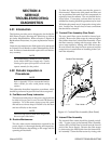
H. Standoff Control
1. Model SC10 Standoff Control
The Standoff Control (SC10) includes an ARC
VOLTS display, a control to set the desired arc
voltage as well as PIERCE HEIGHT, PIERCE DE-
LAY and END OF CUT RETRACT (%). There are
also manual UP and DOWN switches. The Stand-
off Control operates a lifter motor assembly mov-
ing the torch vertically to control torch tip to work
distance.
When used with the Remote Control (RC6010) all
inputs and outputs to the Standoff Control (ex-
cept lifter motor drive) is via an internal ribbon
cable between Remote Control (RC6010) J5 and
Standoff Control (SC10) J7. No additional con-
nections are required between Standoff Control
and Power Supply.
2. Model SC11 Standoff Control
Standoff Control (SC11) is used without a Remote
Control (RC6010). The Standoff Control has ad-
ditional connectors on the rear panel, J40 for CNC,
J41 for EXT PWR and J42 for plasma (labeled PL).
A remote cable connects from the Power Supply
J15 to both J41 and J42 carrying power and sig-
nals to the Standoff Control. Connector J40 ac-
cepts the same CNC cable as the Remote Control
(RC6010) and like the Remote Control it has an
internal terminal strip, J11. Connections J40 and
J11 have only START/STOP, CSD, and OK-To-
Move signals which are optically isolated. A re-
mote cable connects from the Power Supply to
connector J41 supplying the Standoff Control
power. The cable connected to J42 supplies con-
trol signals between Power Supply and the Stand-
off Control. Refer to the individual Instruction
Manuals supplied with the equipment for more
detailed information.
The Power Supply must have an enable switch
connected to the terminal strip, TB2, inside the
Power Supply when the Standoff Control (SC11)
is used.
NOTE
Refer to Appendix VIII for a Signal Flow Block
Diagram of the main functions.
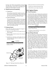
I. Gas Control
The Gas Control (GC3000) consists of additional gas
solenoids mounted on the Power Supply rear panel.
A remote switch box is used to select the desired
Plasma and Secondary gases. Up to four plasma and
three secondary gases can be connected to the mani-
folds and selected by the Gas Control. The secondary
water input to the Power Supply may also be selected
from the Gas Control.
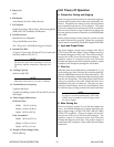
4.04 Troubleshooting Guide
A. Troubleshooting and Repair
Troubleshooting and repairing the this unit is a process
which should be undertaken only by those familiar with
high voltage high power electronic equipment.
WARNING
There are extremely dangerous voltage and power
levels present inside this unit. Do not attempt to
diagnose or repair unless you have had training in
power electronics measurement and troubleshoot-
ing techniques.
B. Advanced Troubleshooting
NOTE
For basic troubleshooting and parts replacement
procedures refer to Merlin 3000 Power Supply Op-
erating Manual 0-2532.