


REPLACEMENT PROCEDURES 40 Manual 0-2533
6. Install the replacement Transformer Assembly by
reversing the above procedure.
C. Main Contactor (W1 or W2) Replacement
NOTE
The Main Contactors, W1 and W2, are replaced in
the same manner.
1. Depending on which Main Contactor Assembly is
to be replaced, remove the Left or Right Side Panel
per Section 5.04-B.
2. Label all the wiring connected to the Main Contac-
tor Assembly.
3. Disconnect the wires from the Main Contactor As-
sembly terminals.
4. Remove the two screws and star washers securing
the Main Contactor Assembly to the Base.
5. Install the replacement Main Contactor Assembly
by reversing the above procedure.
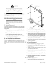
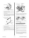
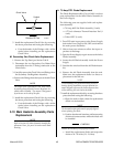
D. Motor (M1) Assembly Replacement
1. Remove the Left and Right Side Panels per Section
5.04-B.
2. Loosen the allen set screw securing the Coupling
to the shaft of the Motor Assembly.
3. Remove the two bolts and nuts securing the Pilot
Resistors, air cooled 4.5 ohms, to the left Pilot Re-
sistor Mounting Support.
4. Remove the two bolts securing the Pilot Resistor
Mounting Support to the Base.
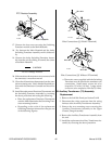
5. Carefully suspend the free end of the Pilot Resis-
tors with string to prevent damage to the resis-
tors.
6. Disconnect the Motor Assembly wiring.
7. Remove the four bolts securing the Motor Assem-
bly to the Base.
8. Remove the complete Motor Assembly out the left
side of the unit.
9. Install the replacement Motor Assembly by revers-
ing the above procedure.
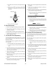
E. Pump Assembly Replacement
1. Remove the Right Side Panel per Section 5.04-B.
2. Disconnect the two Hose Assemblies at the fittings
on the Pump Assembly.
3. Loosen the allen set screw securing the Coupling
to the Pump Assembly shaft.
4. Note the orientation of the Pump Assembly to the
Pump Mounting Plate.
5. Remove the three nuts securing the Pump Assem-
bly to the Pump Mounting Plate.
6. Remove the Pump Assembly from the unit.
7. Install the replacement Pump Assembly by revers-
ing the above procedure and noting the follow-
ing:
• Remove the Fittings from the old Pump Assem-
bly and install on the replacement Pump As-
sembly.
• Be sure to align the Pump Assembly to the Pump
Mounting Plate as noted in Step 4 above.
5.09 Upper Chassis Parts
Replacement
NOTE
Refer to Section 6.08, Upper Chassis Replacement
Parts, for parts list and overall detail drawing.
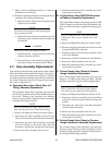
A. Power Driver PC Board Kit Replacement
The Power Driver PC Board Replacement Kit is a di-
rect parts replacement for the failed Driver PC Board
and Switching Transistor (Q1) Assemblies in the
Power Supply.
WARNING
Disconnect primary power at the source before as-
sembling or disassembling power supply, torch
parts, or torch and leads assemblies.
1. Turn OFF main input power to the Power Supply
both at the Power Supply ON/OFF switch and at
the main power disconnect.
2. Wait at least two minutes to allow the input ca-
pacitors to discharge.
3. Remove the top panel of the Power Supply. To
remove the top panel of the Power Supply requires
the removal of several phillips head screws. Care-
fully remove all the screws before attempting to
remove the top panel.
4. Locate the old Driver PC Board Assembly on the
inside left side, behind the front panel, as viewed
from the front of the unit.