


Manual 0-2533 47 REPLACEMENT PROCEDURES
7. Make sure the replacement diode is a direct re-
placement for the old one.
8. Install the replacement diode by reversing the above
procedure and noting the following:
a. Wipe the surface clean where the replacement
diode is to be installed.
NOTE
The thermal interface pads must be properly aligned
when replacing the diode.
b. Position the thermal interface pad between the
diode and contact surface where the diode will
be installed.
CAUTION
Diodes can overheat if not properly installed.
c. Install the diode. Torque the nut securing the
diode to 34 in-lbs (3.8 Nm).
d. Reinstall the nut and washer securing the re-
placement diode wire lead to the PC Board.
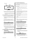
5.11 Hose Assembly Replacements
This subsection describes the replacement of the various
Hose Assemblies used in the Power Supply. The replace-
ment part numbers and detail drawings are in Section 6
as noted in each Hose Assembly replacement instructions.
For a block diagram of the Power Supply Hose Assem-
blies refer to Appendix XV.
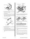
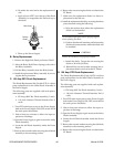
A. Secondary Water Hose (Check Valve to T-
Fitting) Assembly Replacement
The Secondary Water Hose Assembly goes from the
Check Valve on the Secondary Water Solenoid Assem-
bly to the T-Fitting on the Secondary Gas Pressure
Gauge at the front panel. Replace the Hose Assembly
using the following procedure:
NOTE
Refer to Subsection 6.08, Upper Chassis Replace-
ment Parts for part numbers and detail drawing.
1. Remove the Right Side Panel per Section 5.04-B.
2. Disconnect the Hose Assembly from the Check
Valve on the Secondary Water Solenoid Assembly.
3. Disconnect the other end of the Hose Assembly
from the T-Fitting on the Check Valve from the
Secondary Gas Pressure Gauge at the front panel.
4. Remove the Hose Assembly from the unit.
5. Install the replacement Hose Assembly by revers-
ing the above procedure.
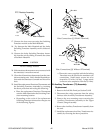
B. Coolant Return Hose (RETURN Connector
to Radiator) Assembly Replacement
The Coolant Return Hose Assembly goes from the RE-
TURN Connector to the inlet side of the Radiator. Re-
place the Hose Assembly using the following proce-
dure:
NOTE
Refer to Subsection 6.05, Front Panel/Cahassis
Replacement Parts for part numbers and detail
drawing.
1. Remove the Right Side Panel per Section 5.04-B.
2. Disconnect the Hose Assembly from the rear of the
front panel RETURN connector.
3. Locate the other end of the Hose Assembly at the
inlet of the Radiator.
4. Disconnect the Hose Assembly from the Radiator.
5. Remove the Hose Assembly from the unit.
6. Install the replacement Hose Assembly by revers-
ing the above procedure.
C. Coolant Supply Hose (Pump to Pressure
Gauge) Assembly Replacement
The Coolant Supply Hose Assembly goes from the
Pump to a T-Fitting at the Pressure Gauge. Replace
the Hose Assembly using the following procedure:
NOTE
Refer to Subsection 6.08, Upper Chassis Replace-
ment Parts for part numbers and detail drawing.
1. Remove the Right Side Panel per Section 5.04-B.
2. Disconnect the Hose Assembly from the T-Fitting
at the rear of the front panel Pressure Gauge As-
sembly.
3. Disconnect the other end of the Hose Assembly
from the Pump Assembly.
4. Remove the Hose Assembly from the unit.
5. Install the replacement Hose Assembly by revers-
ing the above procedure.
D. Coolant Supply Hose (Pump to Pressure
Gauge Connection) Assembly Replacement
The Coolant Supply Hose Assembly goes from the
Pressure Gauge T-Fitting to the front panel Coolant
Pressure Gauge connection. Replace the Hose Assem-
bly using the following procedure: