


Manual 0-2533 15 SERVICE TROUBLESHOOTING
SECTION 4:
SERVICE
TROUBLESHOOTING
DIAGNOSTICS
4.01 Introduction
This Section provides service diagnostics for the Merlin
3000 Power Supply, allowing the Technician to islolate
any faulty Subassemblies. Refer to Section 5, Repairs &
Replacement Procedures, for parts replacement instruc-
tions.
Under no circumstances are field repairs to be attempted
on Printed Circuit Boards or other Subassemblies of this
unit. Evidence of unauthorized repairs will void the fac-
tory warranty.
NOTE
The troubleshooting contained in this manual is
for the Merlin 3000 Power Supply only. Trouble-
shooting other parts of the system is covered in the
separate manuals for that product.
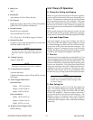
4.02 Periodic Inspection &
Procedures
NOTE
Refer to Appendix XV for a recommended mainte-
nance schedule for water cooled plasma cutting
systems.
This subsection describes inspection procedures which
should be performed at periodic intervals as required.
A. Fan Motor and Pump Lubrication
The fan motor and pump in the power supply should
be oiled twice per year or once for each 100 hours of
operation. To oil the motor, remove one side panel
and add two or three drops of 20 SAE oil to the front
and rear oil holes on the motor.
NOTE
Some units may utilize a sealed motor design which
does not require lubrication.
B. Routine Maintenance
The only other routine maintenance required for the
power supply is a thorough cleaning and inspection,
with the frequency depending on the usage and the
operating environment.
To clean the unit, first make sure that the power is
disconnected. Remove the side panels and blow out
any accumulated dirt and dust with compressed air
especially from the radiator. The unit should also be
wiped clean. If necessary, solvents that are recom-
mended for cleaning electrical apparatus may be used.
While the side panels are off, inspect the wiring in the
unit. Look for any frayed wires or loose connections
that should be corrected.
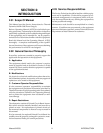
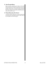
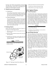
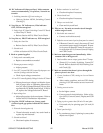
C. Coolant Filter Assembly (Rear Panel)
The rear panel filter screen should be cleaned peri-
odically. Remove the filter screen by unscrewing the
filter holder from the Coolant Filter Assembly. Clean
the filter screen by rinsing with hot soapy water. Re-
move soap residue by rinsing with clean hot water.
Be sure that all the soap has been removed and the
screen is dry of water before re-installing in the Cool-
ant Filter Assembly.
Coolant Filter Assembly
Filter Screen
Filter Holder
A-01018
Figure 4-1 Coolant Filter Assembly (Rear Panel)
D. Internal Filter Assembly
The internal filter screen should be cleaned periodi-
cally. To gain access to the Internal Filter Assembly
remove the Left Side Panel (viewed from the front of
unit) of the Power Supply. Remove the filter screen
by unscrewing the filter holder from the Internal Fil-
ter Assembly. Clean the filter screen by rinsing with