


INTRODUCTION & DESCRIPTION 12 Manual 0-2533
5. Duty Cycle
100%
6. Pilot Modes
Auto-Restart, Pre-Flow Delay, Recycle
7. CNC Signals
Enable Start/Stop, OK-to-Move, Pilot Sensing Relay
(PSR), Full CNC Available with Remote
8. Coolant Pressure
Internal Service-adjustable
130 psi (8.8 BAR) at zero flow
120 - 125 psi (8.2 - 8.5 BAR) at 0.6 gpm (2.6 lpm)
9. Coolant Flow Rate
0.5 gpm (2.2 lpm) with 150 feet (45.7m) of total torch
and torch leads at 70°F (21°C)
NOTE
The flow rate varies with lead length, torch con-
figuration, ambient temperature, amperage level,
etc.
10. Cooling Capacity
4,000 to 10,000 BTU
NOTE
Maximum value based on “free flow” condition.
11. Coolant Reservoir Capacity
2 gallons (8.8 liters)
Capable of handling a total of 150 feet (45.7m) of torch
lead length
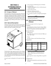
12. Power Supply Dimensions
Enclosure Only -
Width: 24.12 in (0.61 m)
Height: 38.38 in (0.98 m)
Depth: 34.25 in (0.87 m)
Fully Assembled -
Width: 28.50 in (0.72 m)
Height: 43.38 in (1.10 m)
Depth: 43.75 in (1.11 m)
13. Weight of Power Supply Only
678 lbs (308 kg)
3.04 Theory Of Operation
A. Plasma Arc Cutting and Gouging
Plasma is a gas which is heated to an extremely high tem-
perature and ionized so that it becomes electrically con-
ductive. The plasma arc cutting process uses this plasma
gas to transfer an electric arc to a workpiece. The metal
to be cut is melted by the intense heat of the arc and then
blown away by the flow of gas. Plasma arc gouging uses
the same process to remove material to a controlled depth
and width.
With a simple change of torch parts, the system can also
be used for plasma arc gouging. Plasma arc gouging is
used to remove material to a controlled depth and width.
B. Input and Output Power
The Power Supply accepts input voltages from 200 to
575V, 50 or 60 Hz, three-phase. Input voltages are set by
an internal changeover in the unit. The unit converts AC
input power to DC power for the main cutting arc. The
negative output is connected to the torch electrode
through the negative torch lead, and the positive output
connects to the workpiece through the work cable.
C. Pilot Arc
When the torch is activated there is a selectable (2, 4, 7, or
10 second) gas pre-flow, followed by a uninterrupted DC
pilot arc established between the electrode and tip. The
pilot arc is initiated by a momentary high frequency pulse
from the Arc Starter Box. The pilot creates a path for the
main arc to transfer to the work. When the main arc is
established, the pilot arc shuts off. The pilot can auto-
matically restart (factory set for No Auto-Restart) when
the main arc stops, as long as the torch remains activated.
NOTE
For the arc to restart automatically, AUTO RE-
START must be enabled at switch settings inside
the Power Supply.
D. Main Cutting Arc
The Power Supply accepts 50 or 60 Hz three-phase line
input. An internal changeover switches input line volt-
ages in three ranges, for 200/220/230V, 380/415/460V,
or 500/575V operation. The power supply converts AC
input power to DC power for the main cutting arc. The
negative output is connected to the torch electrode
through the negative torch lead. The positive output is
connected to the workpiece via the work cable and clamp
connection.