


Manual 0-2533 13 INTRODUCTION & DESCRIPTION
E. RF Shielding
All machine torch systems are shielded to minimize ra-
dio frequency (RF) interference which results from the
high frequency arc initiation. These shielded systems are
designed with features such as a wire for establishing an
earth ground and shielded torch and control leads.
F. Interlocks
The system has several built-in interlocks to provide safe
and efficient operation. When an interlock shuts down
the system, the torch switch (or control device) must be
used to restart the system.
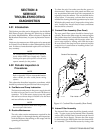
1. Parts-In-Place (PIP) Interlock
The Power Supply has a built-in parts-in-place inter-
lock that prevents accidental torch starting when torch
parts are not properly installed. A flow switch on the
coolant return lead detects reduced coolant flow
caused by improper torch assembly. If not satisfied,
the switch interrupts power to the tip and electrode.
2. Gas Pressure Interlock
Pressure switches act as an interlock for the gas sup-
plies. If supply pressure falls below minimum require-
ments the pressure switches will open, shutting off
the power to the contactors, and the GAS indicator
will go out. When adequate supply pressure is avail-
able the pressure switches close, allowing power to
be resumed for cutting.
3. Thermal Interlock
Thermal overload sensors are located in the Main
Transformer, Main Heatsink Assembly, and Pilot Re-
sistor in the power supply. If one of these compo-
nents is overheated the appropriate switch will open
up, causing the temperature light to turn from green
to red and shutting off power to the main contactor.
When the overheated component cools down the
switch will close again and allow operation of the sys-
tem.
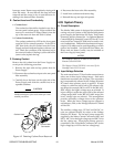
G. Plasma Torches
Plasma torches are similar in design to the common au-
tomotive spark plug. They consist of negative and posi-
tive sections which are separated by a center insulator.
Inside the torch, the pilot arc is initiated in the gap be-
tween the negatively charged electrode and the positively
charged tip. Once the pilot arc has ionized the plasma
gas, the superheated column of gas flows through the
small orifice in the torch tip, which is focused on the metal
to be cut.
The Maximizer 300 Torch uses an internal closed-loop
cooling system. Deionized coolant is distributed from a
reservoir in the Power Supply through the coolant sup-
ply lead. At the torch, the coolant is circulated around
the torch tip and electrode, where the extra cooling helps
to prolong parts life. Coolant then circles back to the
power supply through the return lead. The Maximizer
300 also can use secondary gases such as compressed air,
nitrogen (N2), water, and carbon dioxide (CO
2
).
3.05 Options And Accessories
These items can be used to customize a standard system
for a particular application or to further enhance perfor-
mance. Torch accessories are listed in the separate Torch
Instruction Manual.
NOTE
Refer to Section 6, Parts Lists, for ordering infor-
mation.
A. RC6010 Remote Control
For mechanized systems, this low profile unit provides
full CNC capability and allows the operator to con-
trol most system functions from a remote location.
B. Computer Control Cable Kits
For interfacing the power supply with a computer or
auxiliary control device. Available in various cable
lengths.
C. SC-10 or SC11 Standoff Control
NOTE
Standoff Control SC10 requires installation of Re-
mote Control RC6010.
For machine torch systems, the SC-10 automatically
finds height and maintains torch standoff with a high
speed torch lifter motor.
D. High Pressure Regulators
Available for air, oxygen, argon/hydrogen, nitrogen,
CO
2
and water.
E. High Flow Water Shield (HFWS) Assembly
Reduces arc glare, noise, and fumes during the cut-
ting process.
F. Two Stage Air Line Filter
Removes damaging contaminants as small as 5 mi-
crons from the plasma stream when using compressed
air.