


REPLACEMENT PROCEDURES 38 Manual 0-2533
G. Coolant Tank Replacement
1. Remove the Left, Right, and Top Side Panels per
Section 5.04-B.
2. Drain the coolant from the Coolant Tank per Sec-
tion 4.02-F.
CAUTION
Handle and dispose of the used coolant per recom-
mended procedures.
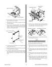
3. Remove the two wires from the Conductivity Sen-
sor located on the end of the Coolant Tank near
the center.
4. Unplug the wiring connection at the Flow Switch
Assembly located on the end of the Coolant Tank
near the top (return hole).
5. Remove the hose connected to the bottom of the
Flow Switch Assembly.
6. Remove the hose connected to the 90° Adapter Fit-
ting near the bottom side (outlet hole) of the Cool-
ant Tank.
7. Remove the four nuts, flat washers and lond screws
that secure the Coolant Tank to the Rear Panel.
8. The parts on the Coolant Tank must be removed
and installed on the replacement per the follow-
ing:
a. Note the orientation of the Flow Switch Assem-
bly to the Coolant Tank.
b. Remove the Flow Switch Assembly from the
Coolant Tank and install it on the replacement
Coolant Tank the same as noted in Step "a".
c. Remove the Conductivity Sensor Assembly
from the Coolant Tank and install it on the re-
placement Coolant Tank.
d. Note the orientation of the 90° Adapter Fitting
in the outlet hole on the bottom of the Coolant
Tank.
e. Remove the 90° Adapter Fitting from the Cool-
ant Tank and install it on the replacement Cool-
ant Tank the same as noted in Step "d".
9. Reinstall the replacement Coolant Tank by revers-
ing the above procedure.
10. Remove the Coolant Tank Cap and Deionizer Bas-
ket from the faulty Coolant Tank.
11. Fill the replacement Coolant Tank with the cool-
ant removed or fresh Thermal Arc Torch Coolant.
12. Place the Deionizer Basket and Bag into the Cool-
ant Tank filler hole and install the Coolant Tank
Cap.
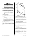
H. Flow Switch Assembly Replacement
1. Remove the Top Panel per Section 5.04-B.
2. Drain enough of the coolant from the Coolant Tank,
per Section 4.02-F, to lower the coolant level be-
low the Flow Switch Assembly hole.
CAUTION
Handle and dispose of the used coolant per recom-
mended procedures.
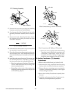
3. Disconnect the wiring connector of the Flow Switch
Assembly from the wiring harness at J25.
4. Disconnect the hose connected to the bottom of the
Flow Switch Assembly in the unit.
5. Secure the end of the hose to prevent coolant from
draining out of the Coolant Tank.
6. Remove the four nuts, washers and long screws
that secure the Coolant Tank to the rear panel.
7. Note the orientation of the old Flow Switch As-
sembly on the Coolant Tank.
8. Move the Coolant Tank forward enough to allow
removal of the old Flow Switch Assembly (see
note).
NOTE
When removing the Flow Switch Assembly leave
the brass fitting in the Coolant Tank.
9. Remove the brass hose fitting in the end of the old
Flow Switch Assembly and install into the replace-
ment Flow Switch Assembly.
10. Install the replacement Flow Switch Assembly, as
noted in Step 7, by reversing the above procedure.
11. Refill the Coolant Tank with the coolant removed
or add fresh Thermal Arc Torch Coolant.
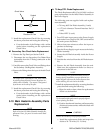
I. Conductivity Sensor Assembly Replacement
1. Remove the Top Panel per Section 5.04-B.
2. Drain enough of the coolant from the Coolant Tank,
per Section 4.02-F, to lower the coolant level be-
low the Conductivity Sensor Assembly hole, lo-
cated on the end of the Coolant Tank.